LTSpice for Windows — introductory tutorial
The circuit for this first LTSpice tutorial is a familiar one. It was used in class, and it is a nice example of a circuit that can be handled using node-voltage, mesh-current, or superposition techniques.

-
Launch LTspice. (A bit of abstract art appears in the program window.) To begin a new circuit, choose "New Schematic" from the File Menu.
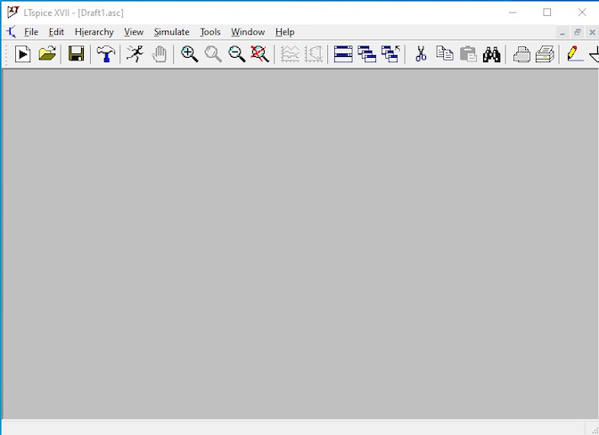
There are many ways to invoke the various actions that will be needed to set up and simulate a circuit.
- There is toolbar along the top of the window with clickable icons for various actions. (Note the figure above shows a truncated view of the window — there are important controls farther to the right on the toolbar.)
- There are menu items for some commands.
- There a keyboard shortcuts that will be place components invoke or invoke various actions. For example, typing "r" creates a resistor and typing "g" creates a ground symbol. There is list of keyboard shortcuts in the "Edit" menu. (They can also be invoked from the Edit menu.)
- We can right-click the mouse and bring up a pop-up menu with various items that can be chosen.
- The function keys will also invoke certain actions.
For any particular thing that we might want to do in LTspice, there may two or three different ways to do it. Each of us will eventually develop our own preferred work flow. Initially, we should make a quick survey of the possibilities. Take a few moments to become familiar with the controls: Click each menu to see the options — the "Edit" menu is particularly important. Hover the mouse over the icons in the toolbar to see what each one does. Hit the "r" or "c" or "v" key to see some of the keyboard shortcuts. (Use "control-z" to undo since aren't ready for any of these yet.) Right-click the mouse to see the options in the pop-up menu.
In the instructions that follow, we will always describe invoking an action by right-clicking the mouse and using the pop-up menu. We do this not because the pop-ups are necessarily the best or fastest method, but because this is the only method that gives access to everything we will need to do. Not every action has a toolbar icon, not every component has a keyboard shortcut, not every command shows up in the menus. In the instructions, trying to list each possible option at each step is just too tedious. So in the instructions, we will describe all actions using the pop-up menu, but we can certainly opt for other controls when they are available. As we learn how to use LTspice, there will be some trial and error, but eventually, we will develop a method that works well for us.
Let's start.
-
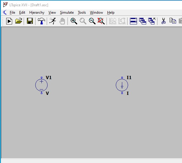
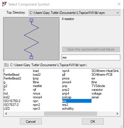
Place the voltage source. Right-click the mouse and choose the "Draft –> Component" menu item. The "Select Component Symbol" dialog opens. You could try clicking around in the component list at the bottom until you find "voltage" (for voltage source), but it is easier to use the search function. After typing two or three letters, the voltage source component is found and the voltage source symbol will appear in the box at upper left.
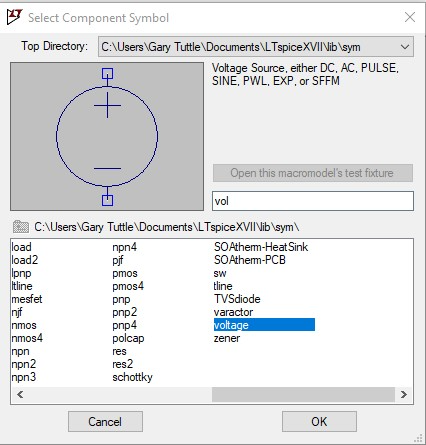
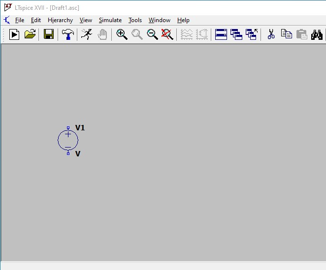
Select "OK". The dialog closes and we are returned to the schematic drawing window. A voltage-source symbol is attached to the cursor. Move the cursor to somewhere in the left-center portion of the window and click to place the voltage source. After clicking, a voltage source will still be attached to the cursor, and we could place more sources if we wanted. Since we need only one source, we can hit the escape key to get out of "placement mode". Note that if we wanted to orient the source horizontally, we can rotate it while it is attached to the cursor by using the key combination "control-R". We can also mirror the symbol using "control-E". (Rotation and mirroring can also be done during the editing step later.) The source has a default name of "V1" and no value – it's just "V". Those could be changed now, but we will wait and make all changes later during the editing phase.
-
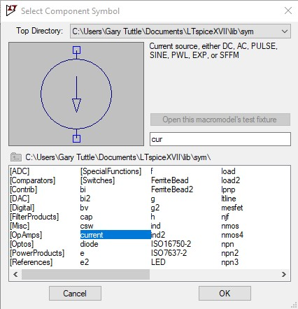
We use the same process to place the current source: Right-click and choose the "Draft –> Component" from the pop-up menu. Start typing "current" into the search box. Once the current source symbol appears, click "OK". The current-source symbol is attached to the cursor — move it somewhere to the right of the voltage source and click to place it. Finally, hit "escape" to stop placing current sources.
-
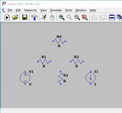
Place the four resistors using the same basic procedure. Right-click and choose the "Draft –> Component" from the menu. Begin typing "resistor" into the search box. When the resistor symbol shows up, click "OK". The resistor symbol is attached to the cursor Rotate it ("control-R"), move it somewhere to the right and above the voltage source, and click to place it. This time, don't hit the escape key yet — continue on to place the other three resistors, rotating ("control_R") as needed. The resistors will be numbered sequentially as they are placed. Once all four are placed, hit the "escape" key to stop with the resistors.
We don't need to be overly careful about placing the components in any particular order or arrangement. Everything can be changed later during the editing step, if needed. If we know how at the outset how we want the schematic to appear, we could save a tiny bit of time by placing components carefully now. But it is not necessary to go over-the-top with pre-planning — if we aren't yet sure of how the final circuit will look, we should slap the compoents down now and fix them later.
-
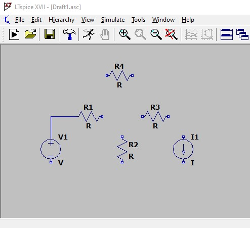
Wire the components together using the wire tool. Right-click and choose "Draft –> Draw Wire" from the menu. The cursor turns into a giant set of cross-hairs that extend across the entire window. These are helpful in aligning the placement of the wires. Move the intersection of the cross-hairs to the terminal at the top of the voltage source and left-click on the terminal to start the wire. Move the cursor up to draw a vertical section of wire, left-click again to place a "corner", and move right towards the left end of resistor R1. Left-click on the left-hand terminal of the resistor to end that section of wire. The first bit of wiring should like something like the figure below. If we mess up, we can hit the "Escape" to stop and use "Undo" or "Delete" to remove any bad wires.
Continue wiring to connect all the other components according the original circuit digram. In addition to ending on a component terminal, we can connect to an existing wire to make a T-connection, which is indicated by a small square dot. (Similar to the circular dots used to show wire connections in the class notes.) When finished hit the "Escape" key to drop out of wiring mode.
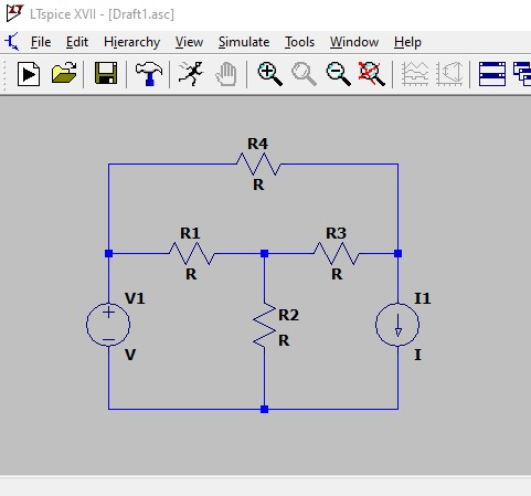
Wiring pro tip: It is not necessary to wire from terminal-to-terminal, stopping and clicking at each point. LTspice has a speed wiring mode, in which we can draw the wires right through components. It looks wrong as we do it, but once we stop to click at a corner or intersection, the program automatically makes connections for the components that were "drawn through". Using this trick can speed things up a bit. In fact, in LTspice, we can draw the wires first and then add the components. In that case, we would drag the components on top of the wires and the LTspice will make the connections automatically. If a circuit is laid out in nice rectangular meshes — as our 201 circuits often are — drawing the wires first might be faster than placing the components first. We give it a try — we might like it.
-
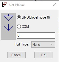
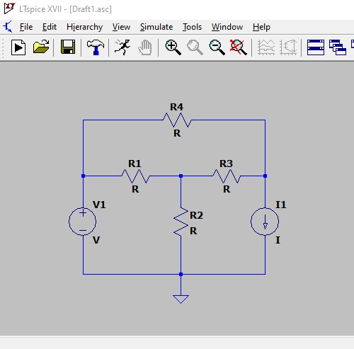
Add the ground connection. Every SPICE circuit needs a ground connection. It can be at any node, but there must be one. (A common SPICE user error is forgetting to include a ground — LTspice will give us an error message at simulation if there is no ground.) Right-click and choose "Draft –> Label Net" from the menu — a Net Name dialog appears. Select "GND (global node 0)" and click OK. Back in the drawing window, a ground symbol is attached to the cursor — move it to the desired location and left-click to place it. Then use the wire tool (from step 5 above) to wire it to the rest of the circuit.
We can have multiple ground symbols in the schematic. Every ground symbol will be treated as being to connected to the same node (node 0) in the circuit — there does not need to be an explicit wire connecting all the ground points. Using multiple ground symbols can help clean up a complicated schematic.
After all the ground connections have been placed, hit the "escape" key to end "ground mode".
Now we are ready to enter parameter values and do any desired editing of the schematic layout.
The specific values for the components must be entered. If desired, the reference names for the components can be changed. Also, any changes to the circuit layout can be done now.
To change component values: hover the mouse over the value text — the cursor changes to an "i-bar" — and then right-click to bring up a dialog where the value can be changed along with the font size and justification. Enter the desired value. As opposed to what is preached in class, SPICE treats units are optional — you can enter units, but they will be ignored. SPICE knows that a voltage source needs a value in volts, a resistor needs a value in ohms, etc. Pre-fixes can be used and are encouraged. For example, a 1000-Ω resistor could (and probably should) be listed in SPICE as 1k.
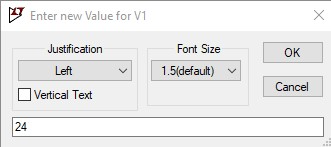
Changing component reference names is done in the the same manner as changing values. Note that in SPICE, reference names "should" have the first letter correspond to the type of component, followed by letters and numbers to distinguish individual parts. For example, Vxxx for voltage source, Iyyy for current source, Rzzz for resistor, etc. However, in LTspice the standard convention is not mandatory, and if we would like to name the voltage source "bill", it will work. (LTspice does adds a "V" in front of "bill" when the netlist is built.)
Use tools in the "Edit" item of the pop-up menu to move components, move text ( names and values), re-configure the wiring, or delete anything. A few comments/hints:
- "Undo" is your friend. If you make a mistake during the initial layout or wiring, simply undo and start over.
- To enter an editing mode, first move the cursor away from any components so that it is in an open area of the drawing window. Then right-click and select the desired editing tool. If the cursor is above a part when right-clicking, a dialog opens in which more detailed information about that part can be entered — we don't need that now.
- There are two options for shifting the location of parts and text, "move" and "drag". To invoke either, right-click and choose either "Edit –> Move" or "Edit –> Drag". Then left-click on the particular part to attach it the cursor so that it can shifted. Shift it to the new location and left-click again to lock it into place. The difference is that "Move" will pick up the part and dis-connect it from any wires. You would then have to delete the old dangling wires and re-wire the part back into the circuit. Using "Drag" will move the component along with the wiring, re-routing as best it can to the new location. After dragging a component, the connecting wires will probably run at random angles. We can also drag wire corners to clean things up.
- If we want to shift a group of components, we can drag the cursor across a group of compenent to select them all simultaneously and then shift them (either moving or dragging) en masse.
- The functions "Delete" and "Duplicate" work as expected. Right-click and choose either from the "Edit" pop-up, and then left-click on the component, text, or wire to be deleted or duplicated. The duplicated item can then be moved to the desired location.
When moving values, names, or other text — things that don't have wires attached — "Move" and "Drag" function identically.
Below is the circuit after changing names and values. (The basic layout was not changed.)
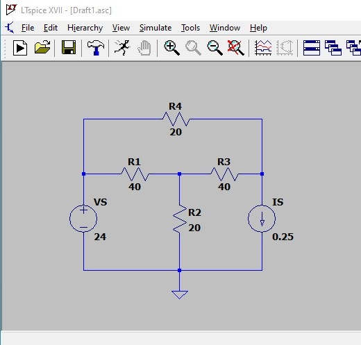
Next we tell LTSpice what type of analysis we would like it to do. LTSpice is a bit unique in that it uses the text commands from the original text-based version of SPICE and embeds them right into the schematic. Other renditions of SPICE use dialogs to set up the simulation and keep the actual SPICE command hidden. LTspice boldy puts the directive text front and center, but we are required need to know the details of the directives.
For this circuit, we are keeping it simple and want only to find the DC values of the voltages and currents in the circuit. In SPICE, a simple DC analysis is known as an "operating point" simulation, and the relevant directive is ".OP".
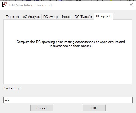
In this case, we make an exception and describe methods for entering directives, since the two are quite different. The first is through a dialog that is invoked using the "Simulate —> Edit Simulation Cmd" menu item (in the window menu bar). The dialog has several tabs across the top. Choose the "DC op pnt" tab — ".op" appears in the text box at the bottom. Click "OK" and we are returned to the drawing window, with ".op" attached to the cursor. Click to place it anywhere in the drawing window.
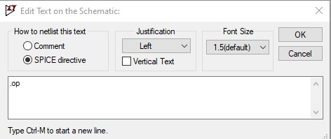
We can also enter the directive command directly. Right-click and choose "Draft –> SPICE Directive" from the pop-up menu. In the dialog box that opens, type ".op". (Either upper or lower case is fine.) Hit return and place the directive text somewhere in the schematic drawing window.
When the simulation starts, LTSpice will look for the directive text to determine what to do. We will look at other analysis types (transient, DC sweep, AC sweep) in future examples in 201 and in 230.
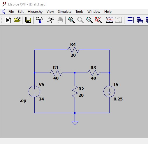
Run the simulation and see the DC results
Finally, we are ready to run the simulation and see the results.
Before doing that, it might be a good idea to name the schematic and save it on the disk, if that was not done earlier. (At this point, it would be a shame to lose everything due to some random failure.)
To begin the simulation, select the "Run" menu item. Or click the "Run" icon in the toolbar. The simulation will be done in a second or two. (SPICE is very speedy at node-voltage analysis.)
A window will appear with a list of the DC operating point values — the voltages at each of the nodes with respect to ground and the currents through each of the components.
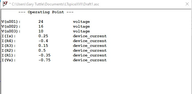
Note: Current directions are a bit tricky. SPICE always reports the current flowing in the direction from the first listed node to the second listed node in the netlist. However, since the netlist is generated by the program based on the schematic, we don't know how SPICE is "drawing the current arrow", unless we look at the netlist. Usually, that's not worth the trouble. instead use KCL and KVL to confirm every balances using the magnitudes and the reported node voltages.
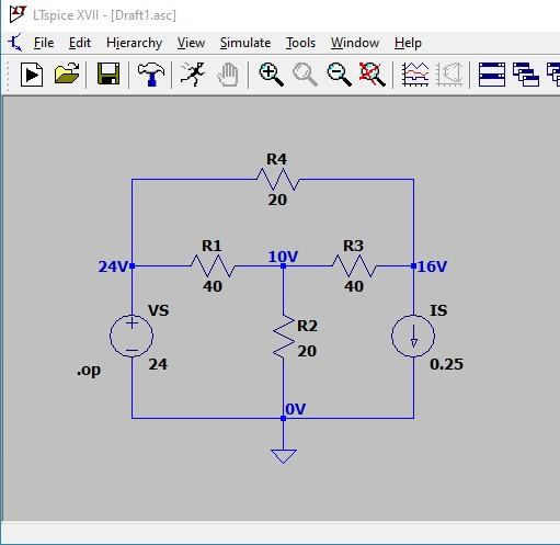
We can also have the DC values displayed directly on the schematic. (As we might when doing hand calculation with Kirchoff's laws to find the various quantities.) Go back to the schematic and hover the cursor over a node. Hold down the left button, and the cursor turns into a tiny "voltage probe". When the button is released, the corresponding voltage is printed in the schematic next to the node. This can be done at each of the nodes — the resulting view is shown below.
We can list the currents through the components. The "hover-and-click" method doesn't work here. Instead, right-click and choose to the ".op Data Label" menu item. This open a dialog which allows us to choose any of the DC quantities to paste into the schematic window. Let's choose the voltage-source current — click on "I(Vs)" in the list and that text appears in the text box at the bottom.
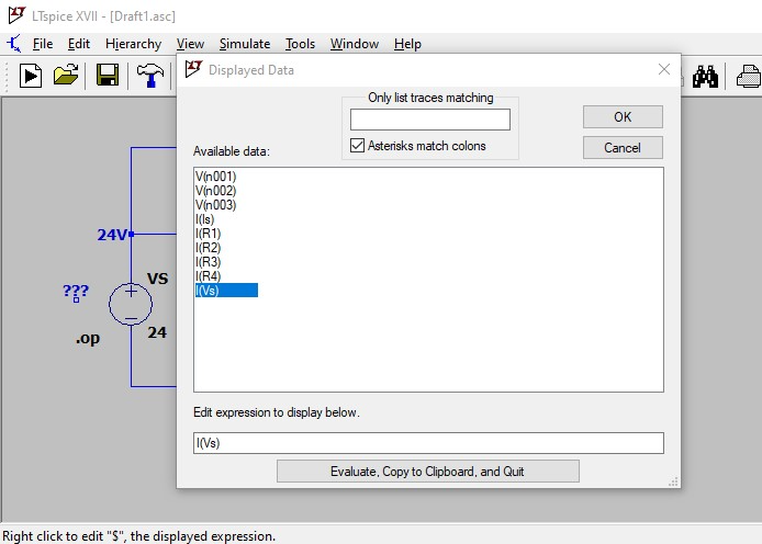
Click OK, and then we can place the current value somewhere convenient in the schematic window. We can add as many different quantities as we might like. (The node voltages could have been done through this dialog box as well.) The figure below shows the schematic displaying all the node voltags and the current through the voltage source and the resistors currents through R2 and R4. (Note: I have not yet found a way to control the significant digits. If LTspice were taking an EE201 quiz, I would probably make a "red-mark comment" about the silly use of significant digits.)
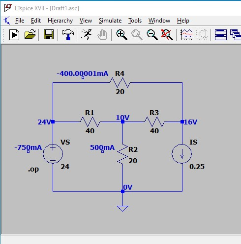
That's pretty much all there is. If these are the needed results, we can copy and paste the circuit and the results into a report. If there is more to be done, we can change the circuit or the component values and re-run the simulation to see how the results change. Or we could change the sources and run a different type of simulation. That's the beauty of SPICE — once the basic circuit has been created, we can simulate to our heart's content.
When we are finished with simulations for this circuit, we should save the schematic to disk, and then shut down LTSpice. If we need more simulations with this circuit later, we can re-open the schematic and continue from where we left off.