ISU Audio and Arduino Club
Battery Checker build instructions
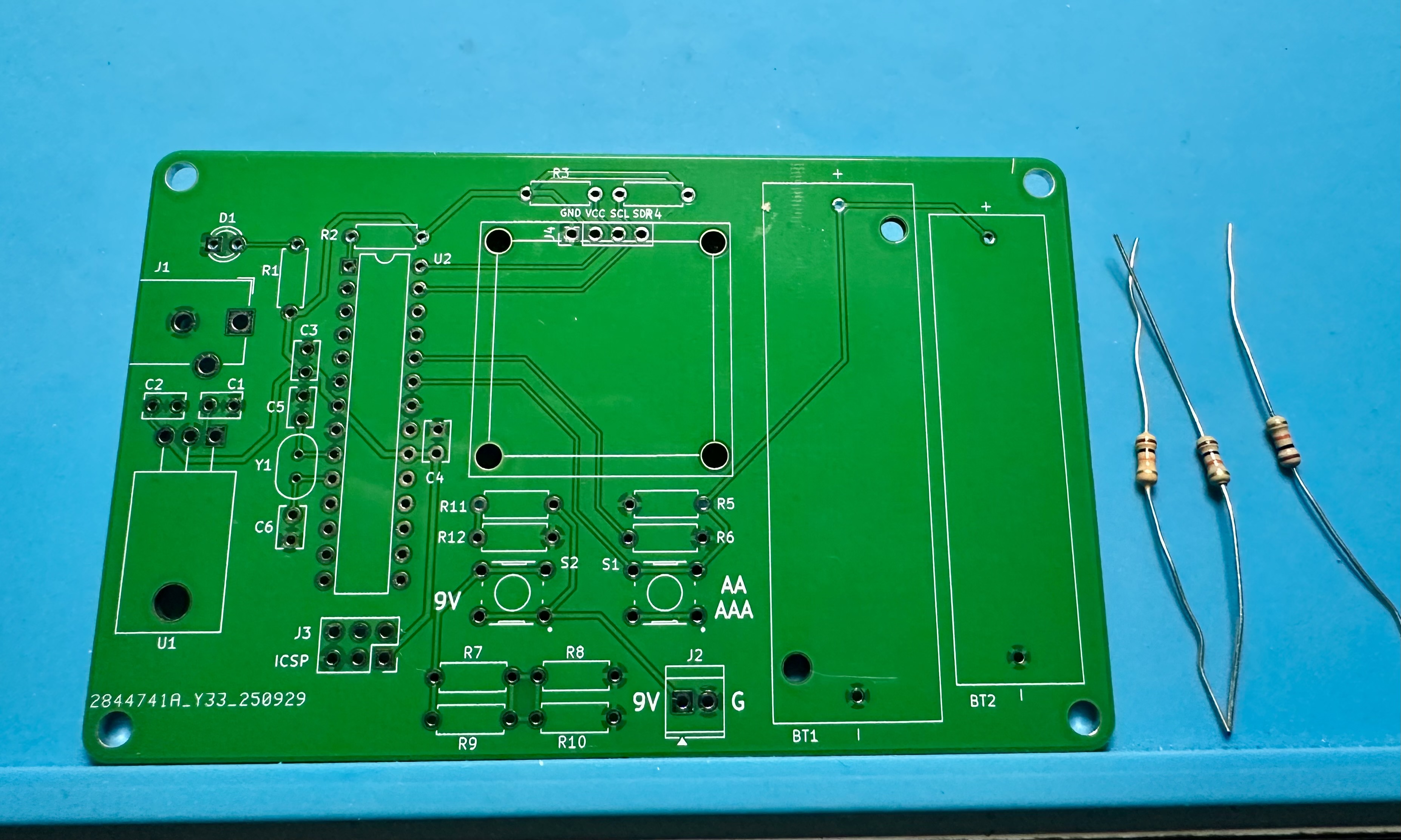
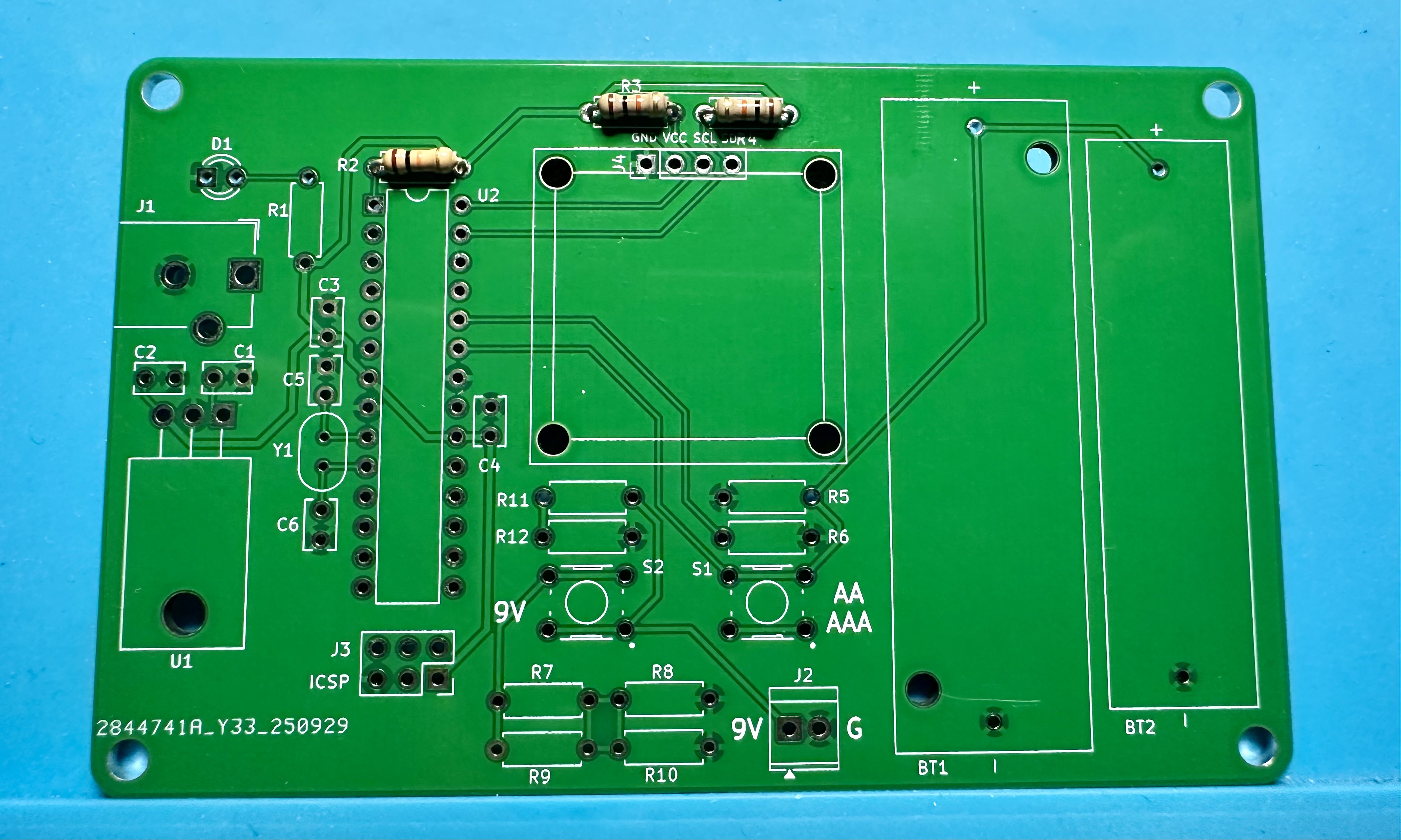
- Below are step-by-step instructions for building the Battery Checker project. The PCB is fairly simple and should be easy to solder. There is really nothing tricky about any of it. It should be somewhat familiar if you did the Resistometer project.
- The order of assembly given below is a suggestion — there is nothing wrong with soldering the parts in a different order.
- The usual tools are required: solder and soldering iron, needle-nosed pliers for manipulating parts and pulling leads through holes, and wire cutters for trimming leads after soldering. Helpful but not essential would be a vise for holding the boards and a magnifying glass and light for viewing small print.
- To view the photos at higher resolution, open the images in a new tab or window.
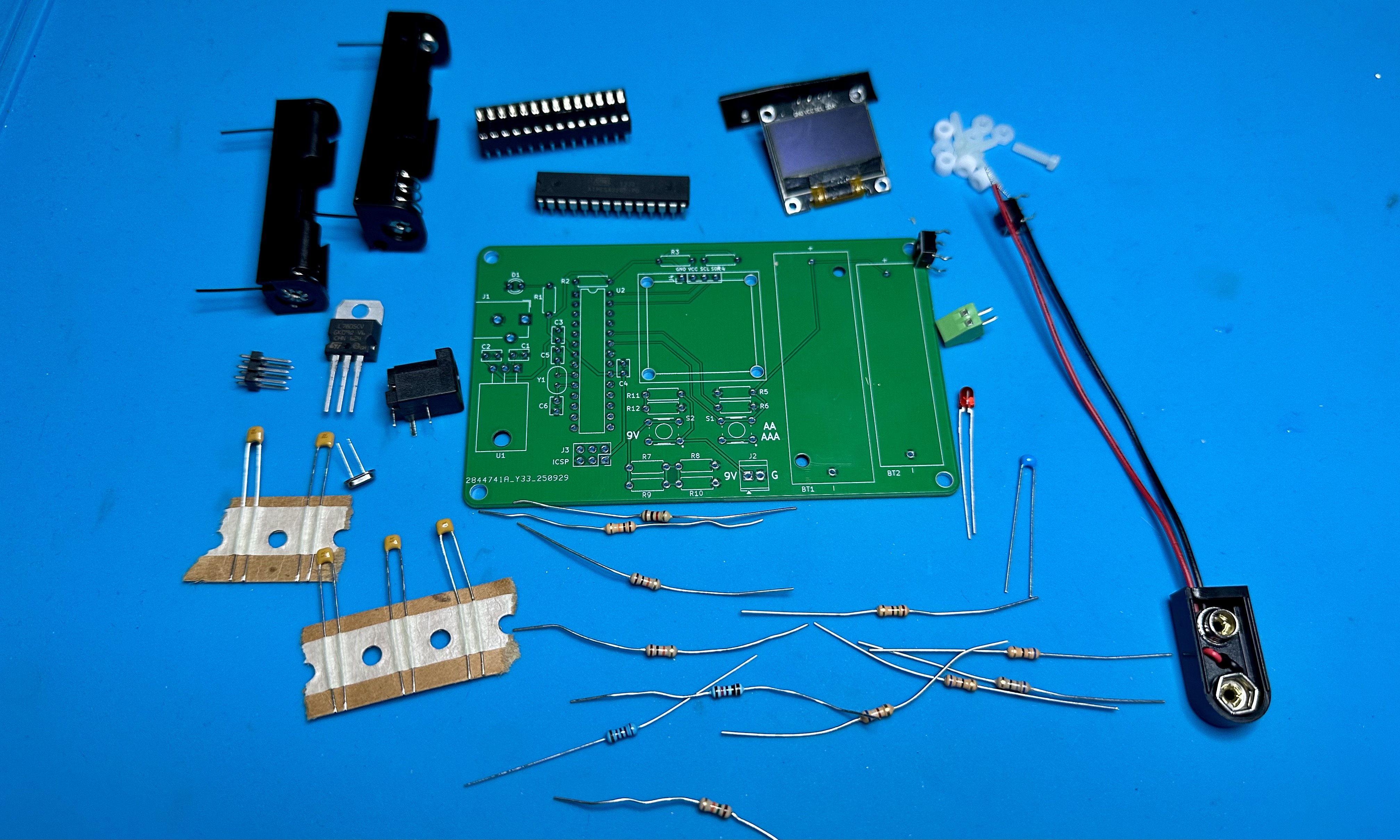
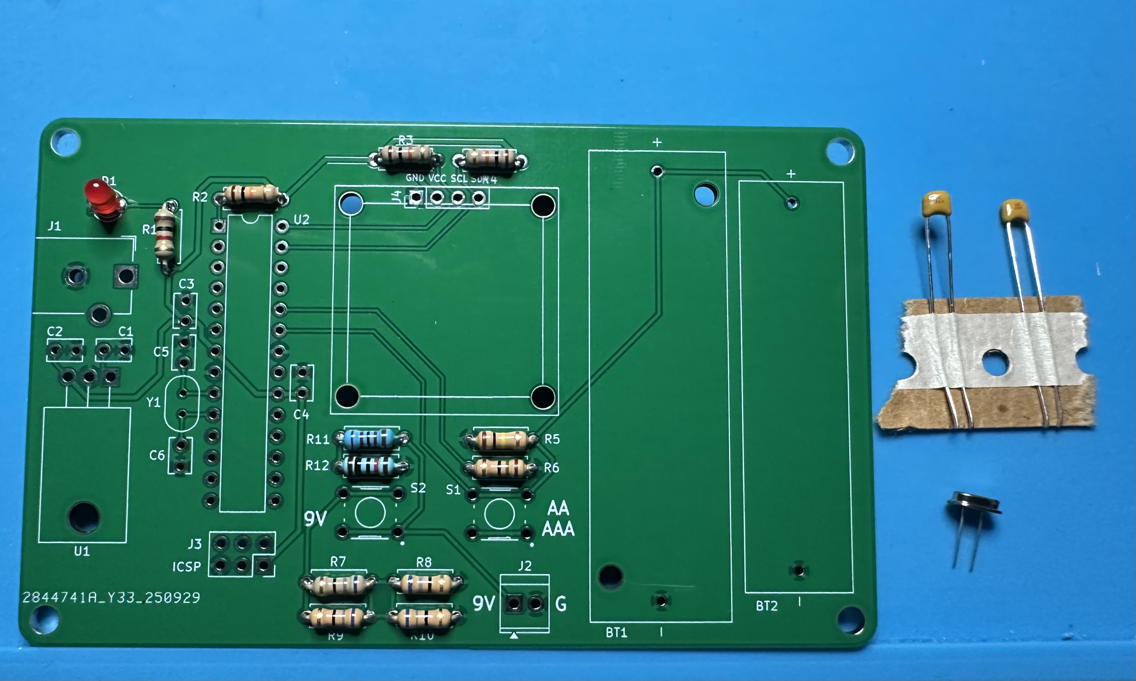
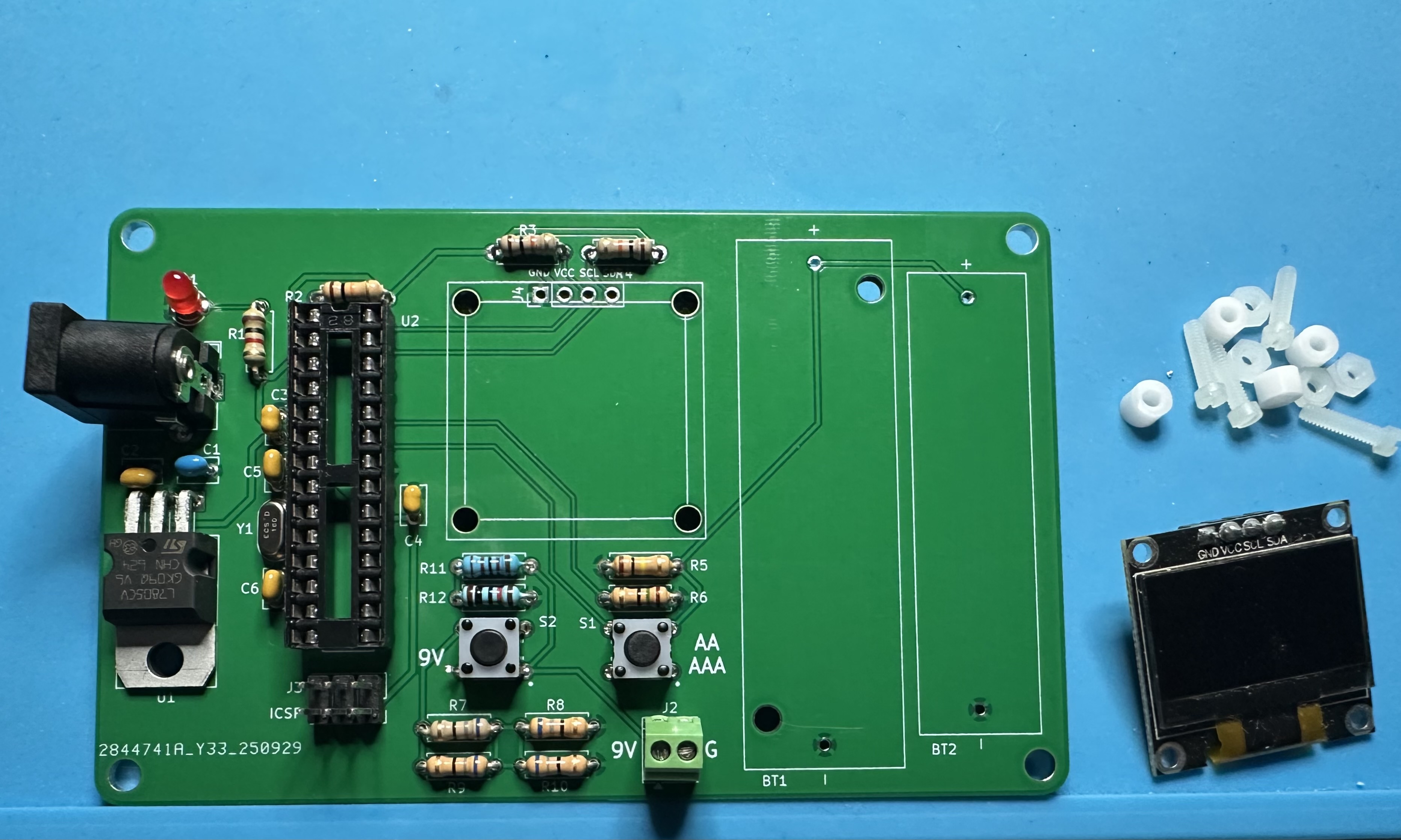
- Assemble the parts. (See the BoM for the complete list.)
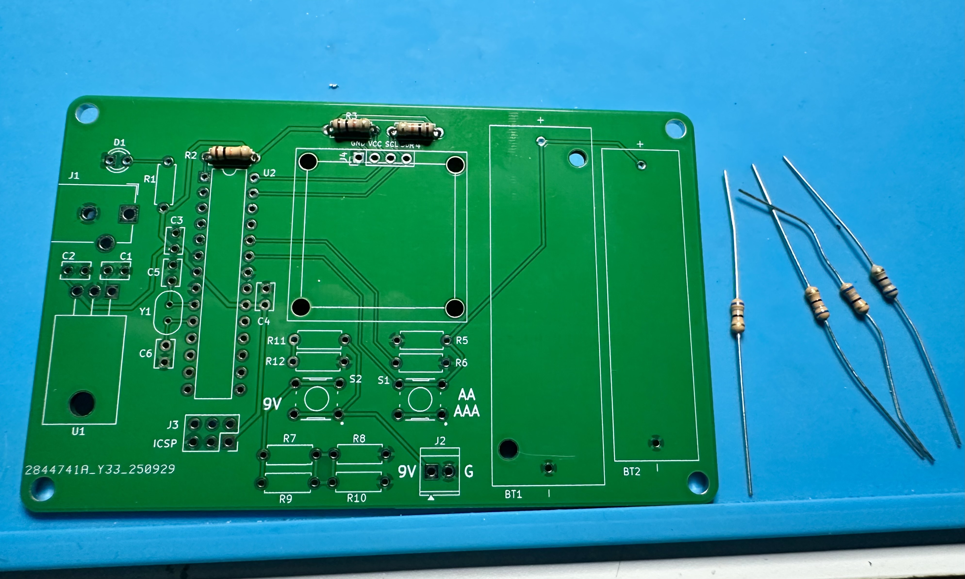
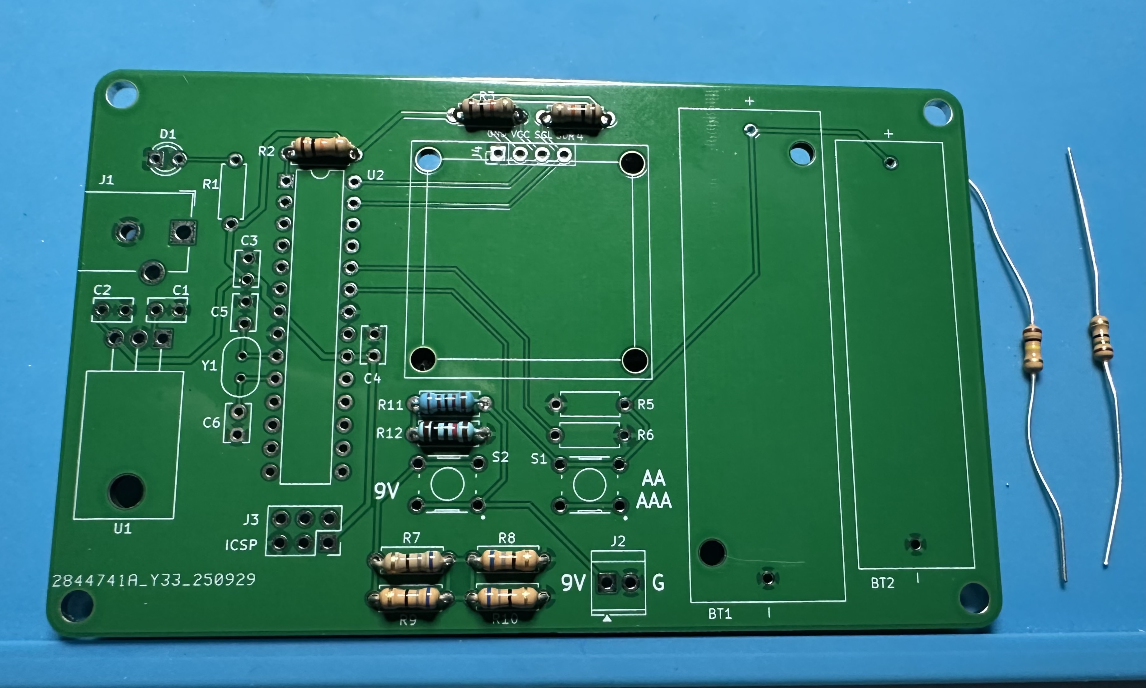
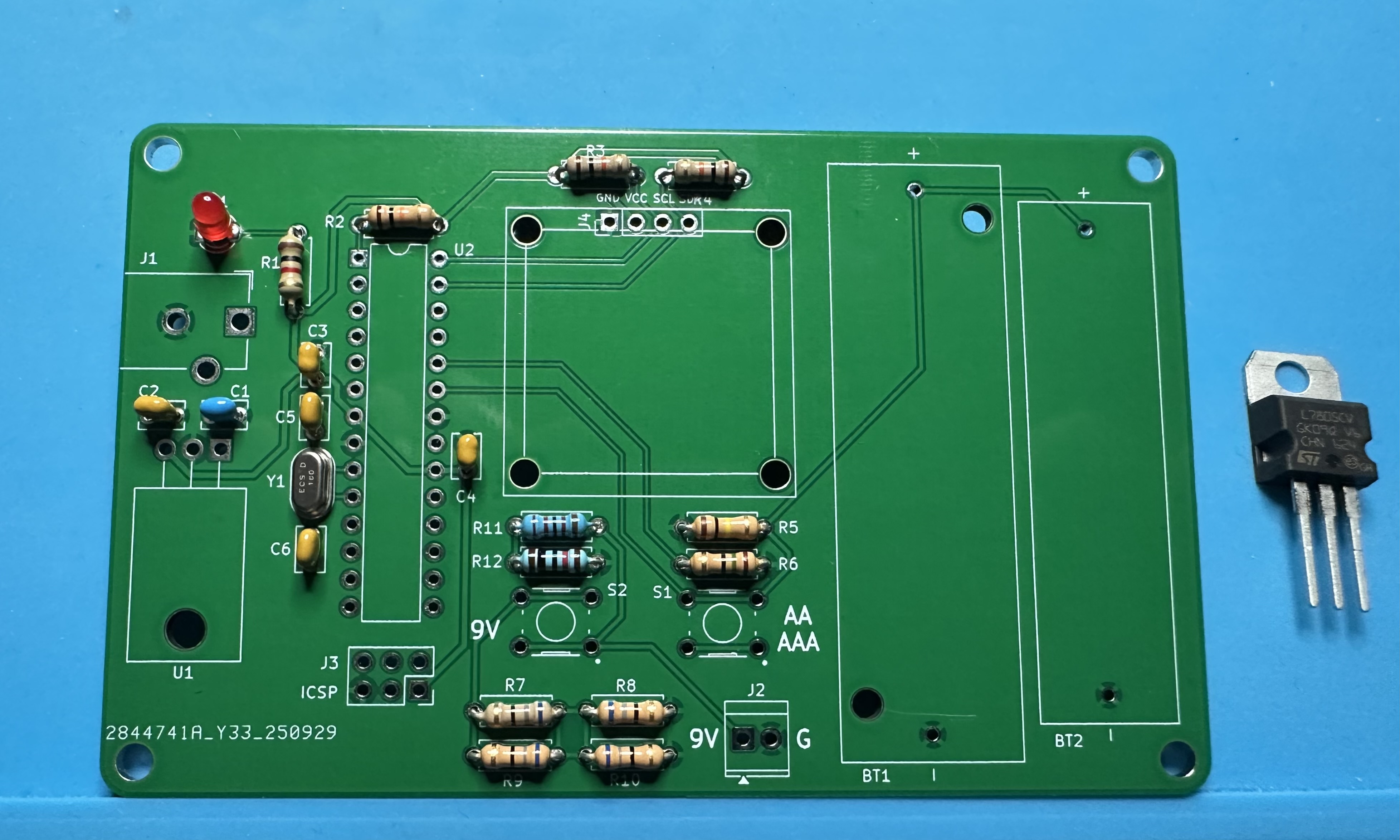
- As usual, we start small and work our way to the bigger parts. The three 10-kΩ resistors (5%, brown-black-orange) resistors are easy to do. Two are pullups for the I2C serial communications channel (R3 and R4 — the R4 label is partly obscured) and one is the pullup for the Atmega reset (R2).
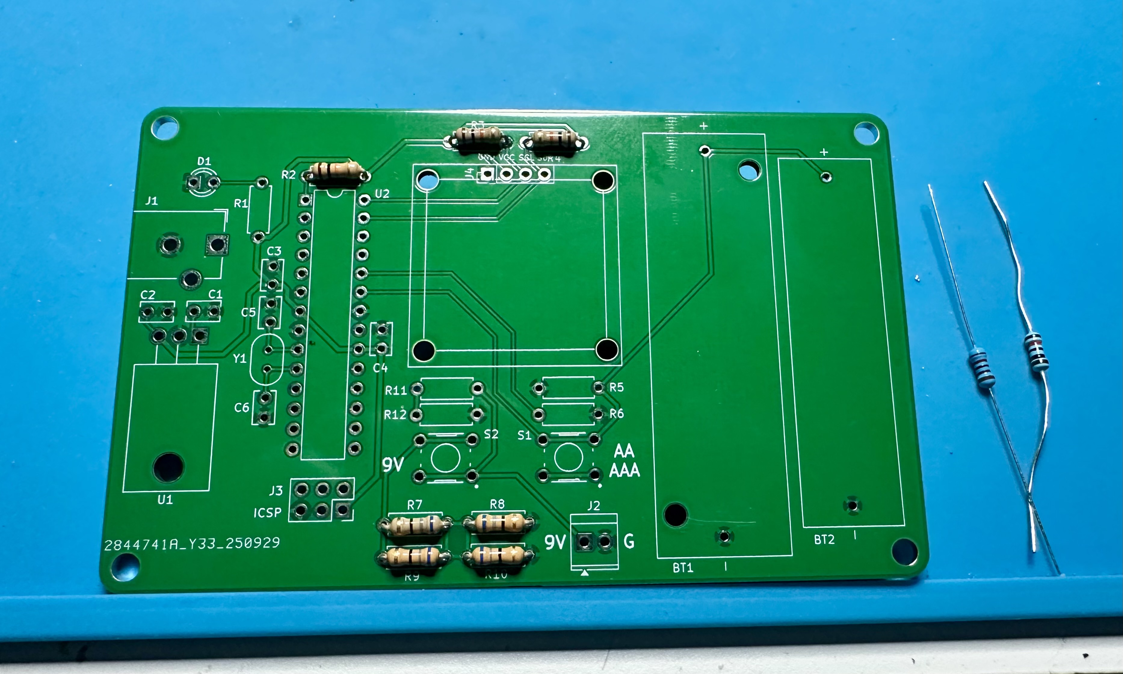
- Now add the four 82-Ω, 1/4-W resistors that are used to make an effective resistance of 82 Ω but that can handle 1 W. These are labeled R7 - R10. (Sharp-eyed observers might note that the resistors in the photo are 68 Ω. I didn't have enough 82-Ω resistors at home. – GT)

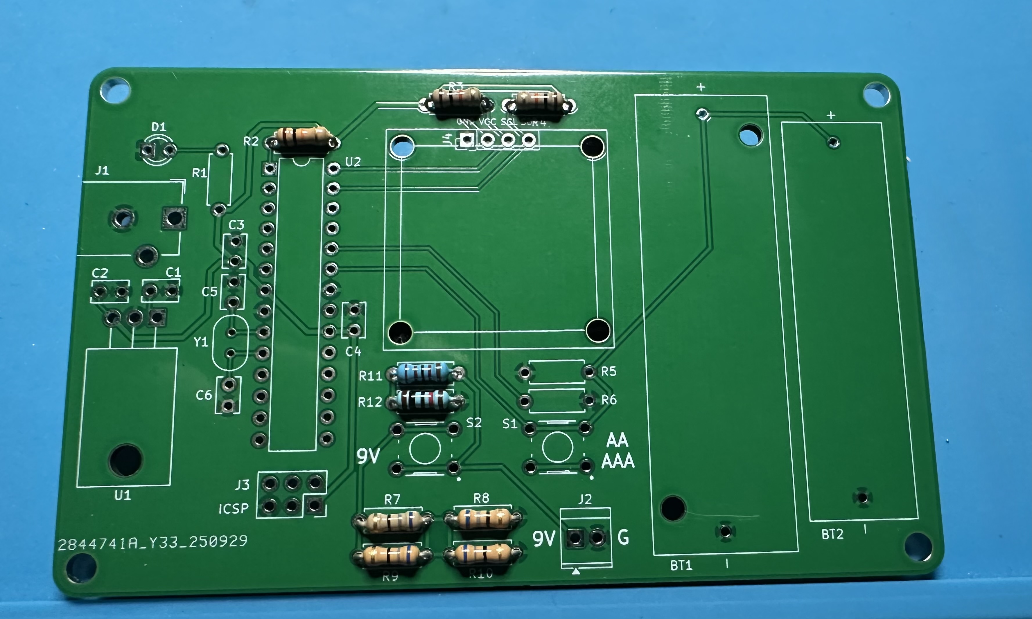
- Next, add the two resistors that make up the voltage divider used to measure 9-V batteries. R11 is 22 kΩ (red red black red) and R12 is 10 kΩ (brown black black red). Both are 1% resistors. (Use the ohm-meter to measure them if you are unsure which is which.)
- Add the two resistors used for measuring AA and AAA batteries. R5 is 100 kΩ (brown black yellow) and R6 is 15 Ω (brown green black). Both are 5% resistors.
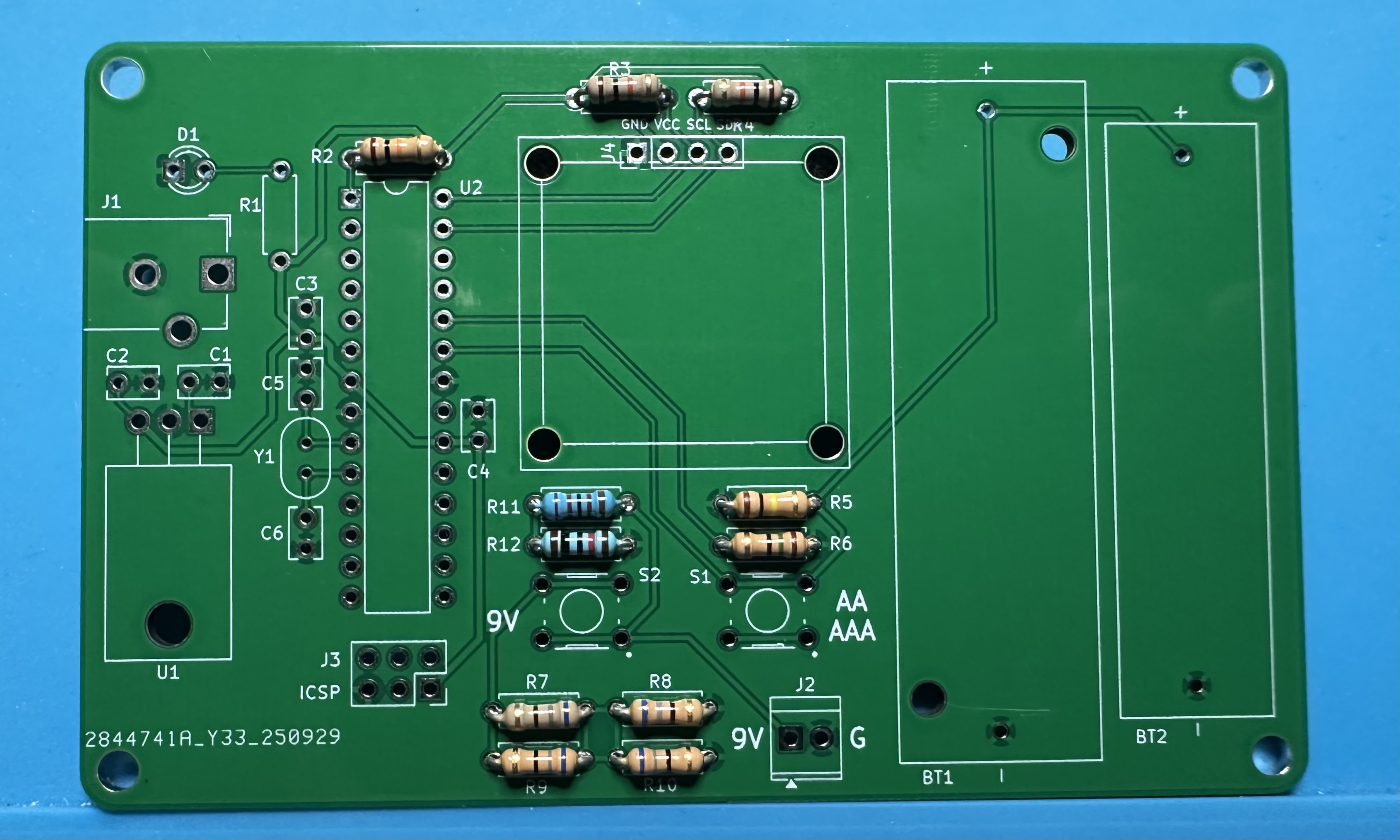
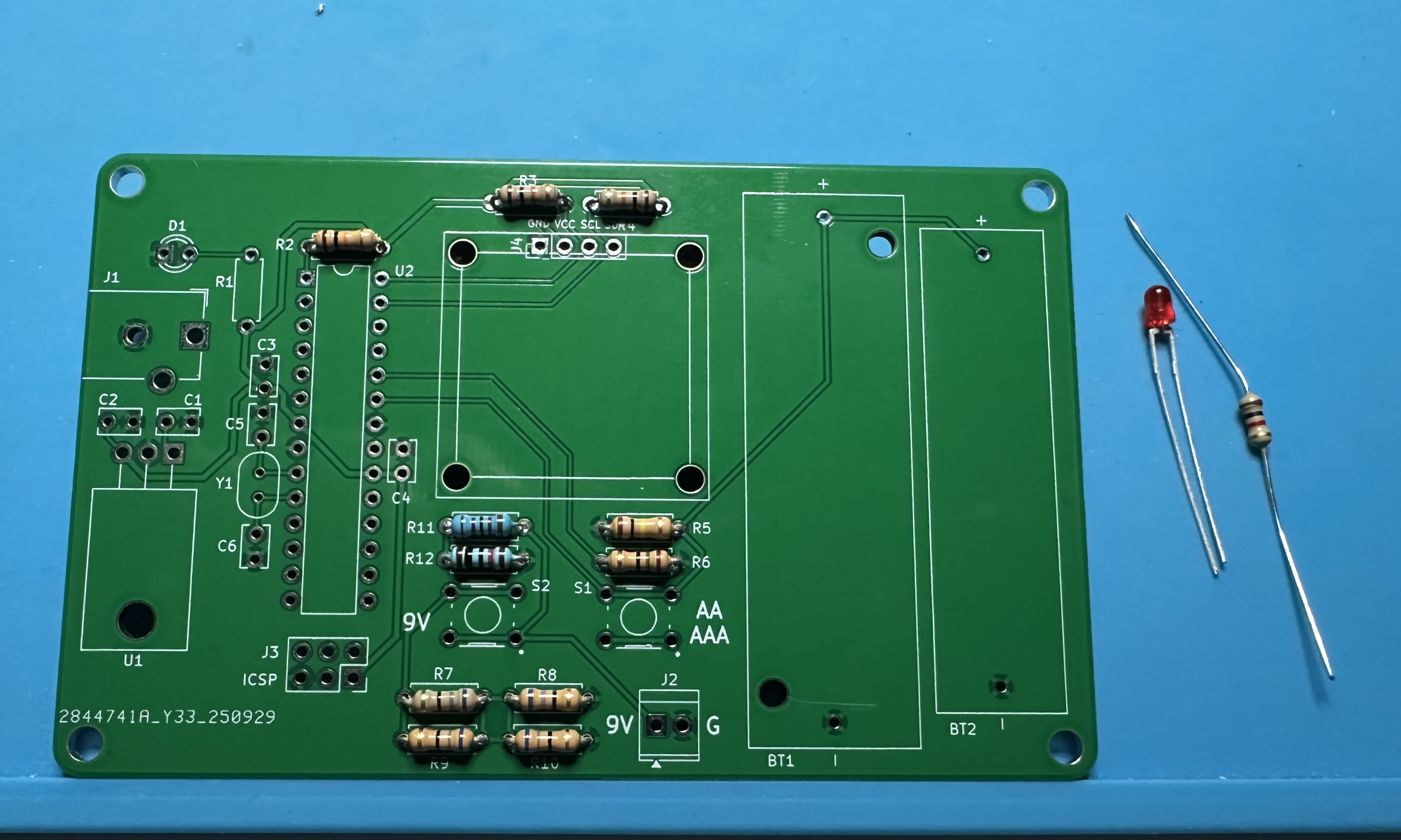
- Now we can install the "power on" LED D1 and its 1-kΩ limiting resistor (brown black red) in R1. The LED is directional — it must be soldered in with the correct orientation. The longer lead is the anode (positive) and goes in the circular through hole. The shorter lead is the cathode (negative), and it goes in the hole with the square outline.
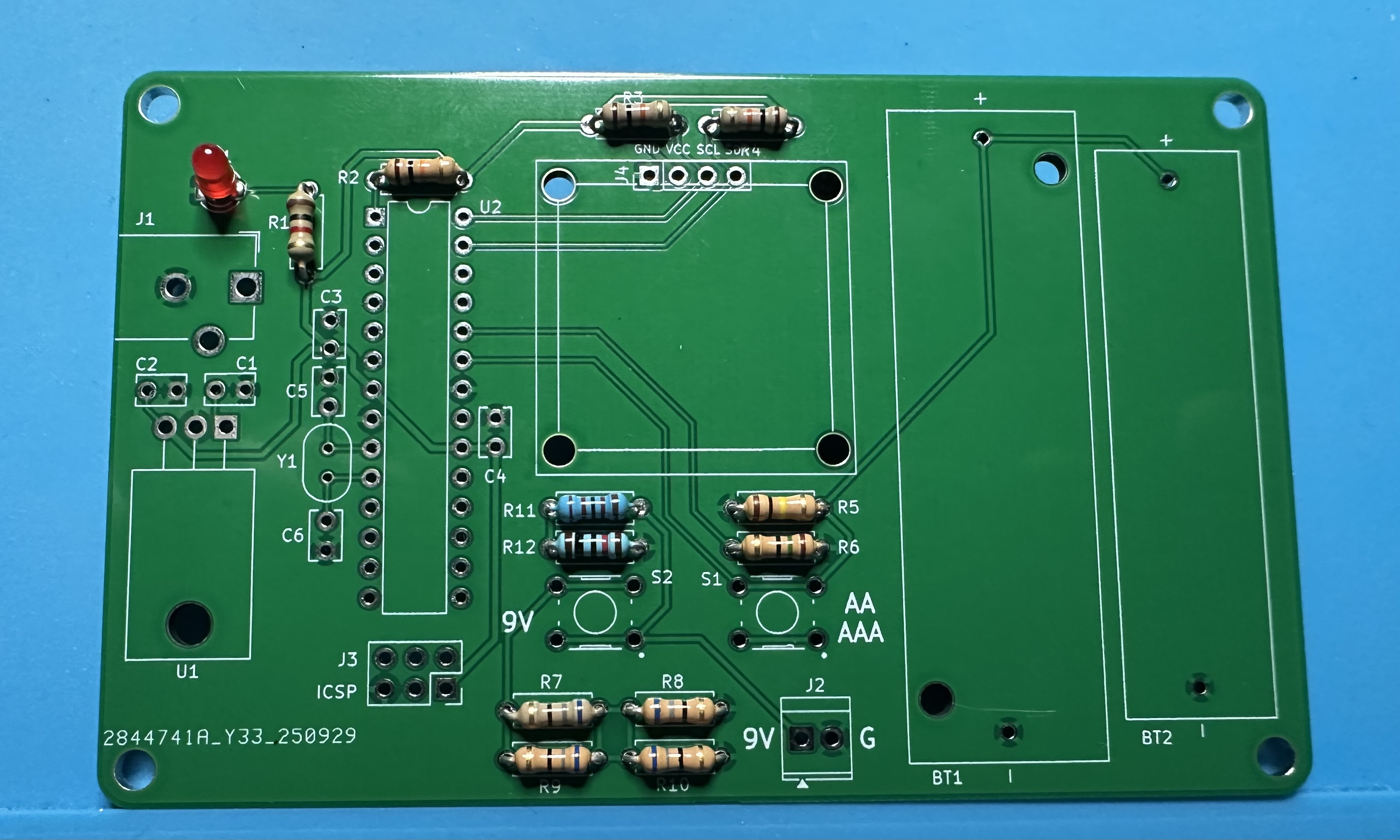
- Up next, the 16-MHz oscillator crystal (Y1) for the microcontroller and associated 22-pF (22J) capacitors (C5 and C6).
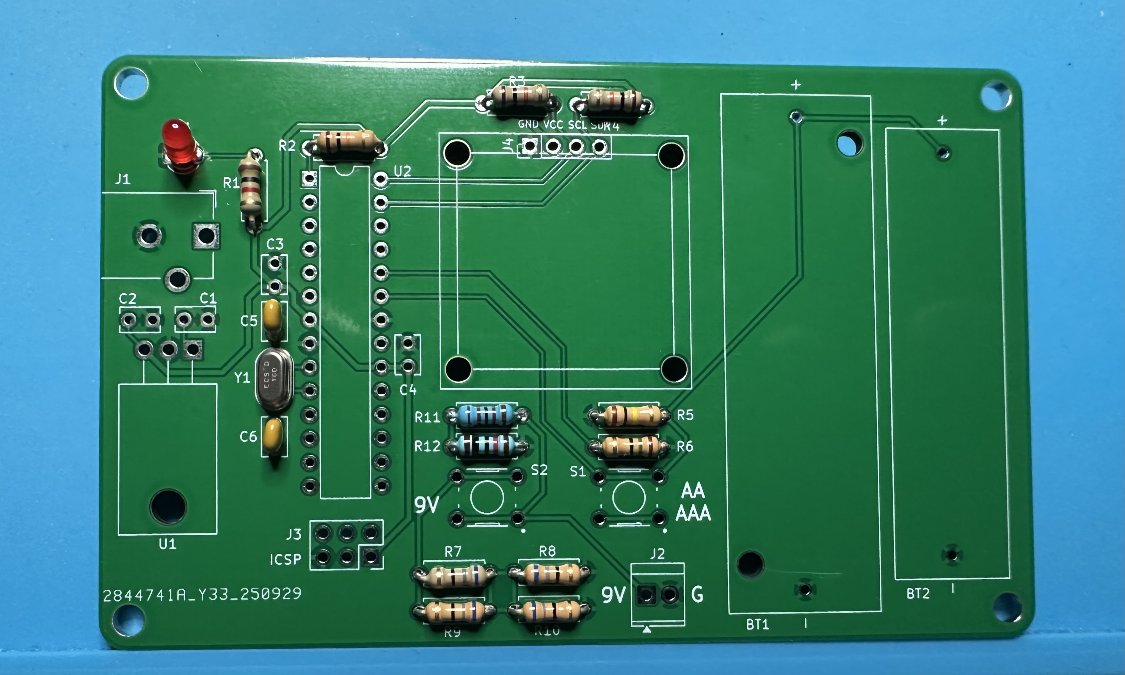
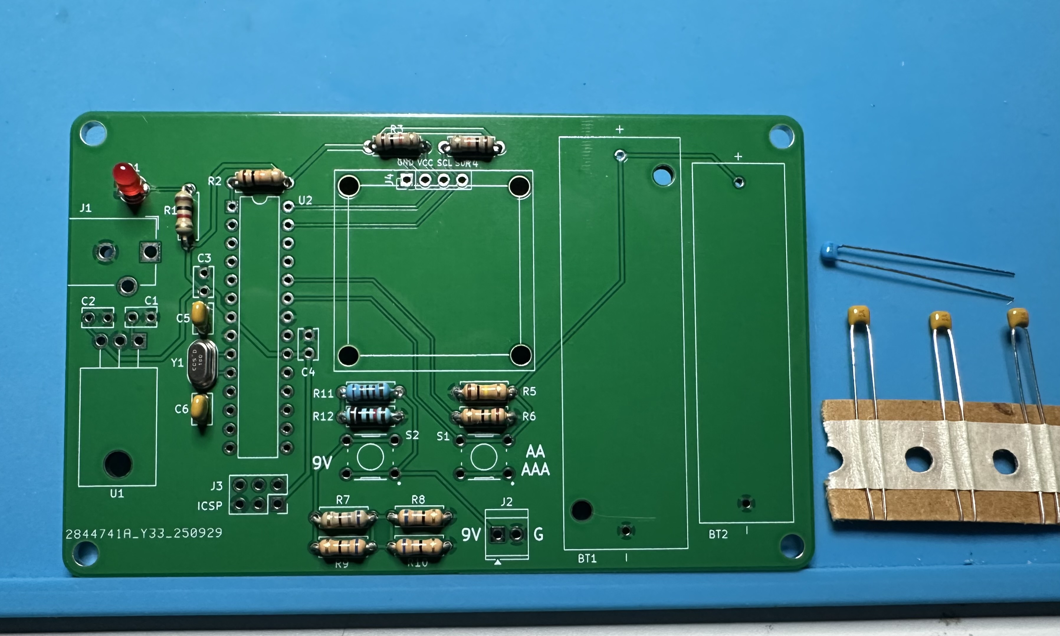
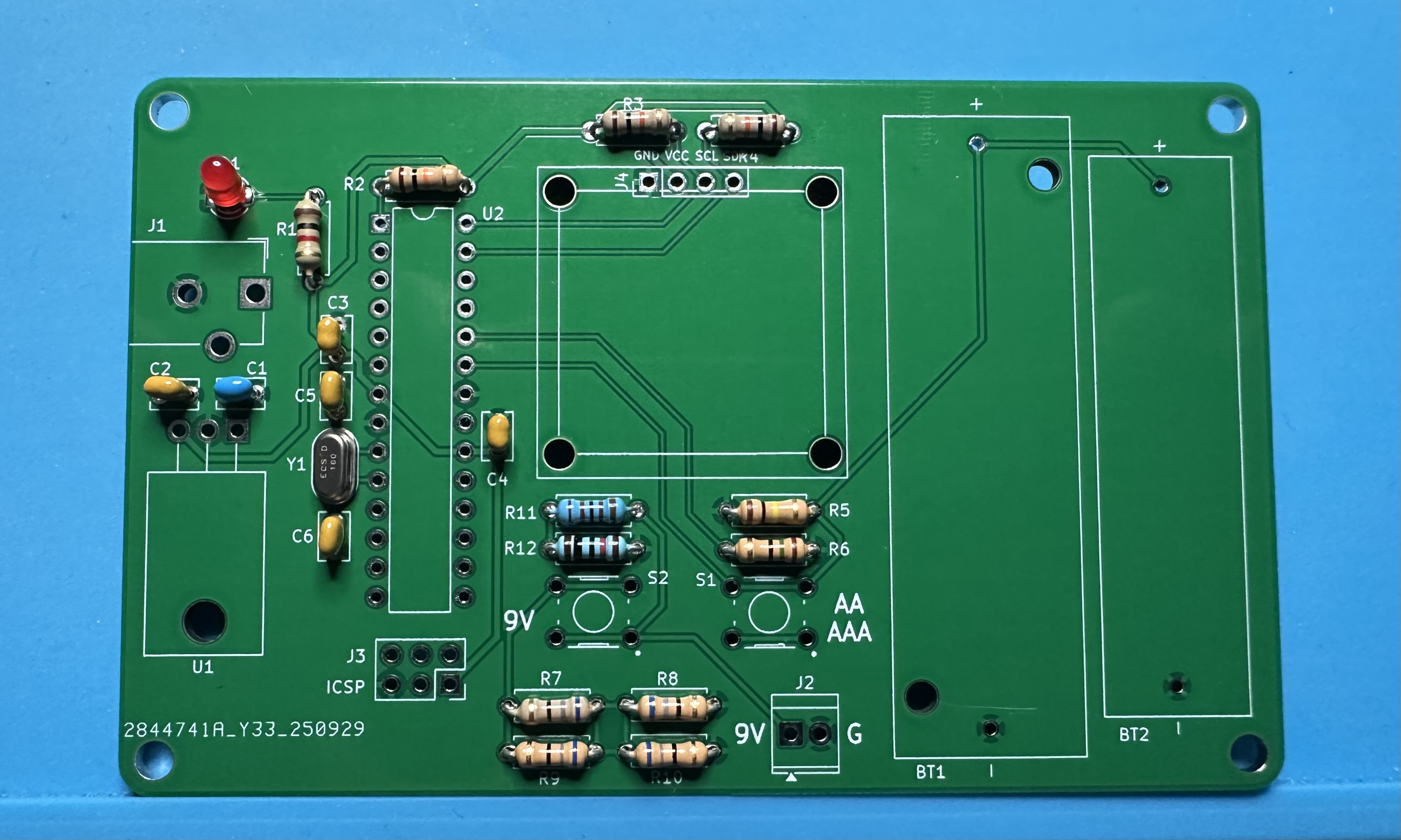
- Add four small capacitors. Two 100-nF (104) capacitors for Atmega bypassing (C3 and C4), a 0.33-uF (334) capacitor for the input of the voltage regulator (C1), and one 100-nF capacitor on the output of the regulator.(C2).
- The LM7805 voltage regulator, U1. You can leave it standing straight up or bend the leads so that it lays down flat, as shown here. You will probably have to fiddle with the bending a little bit to get a good fit.
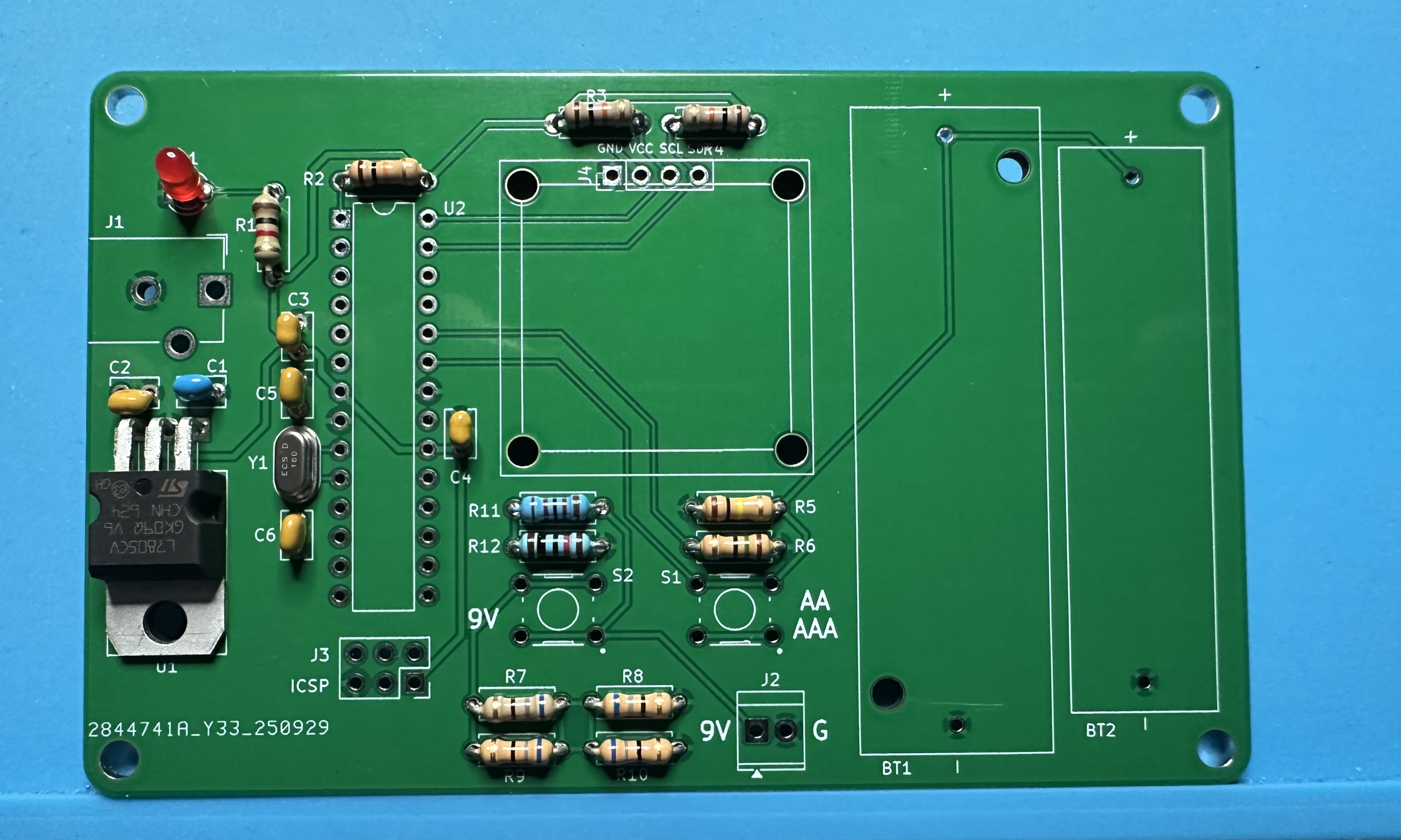
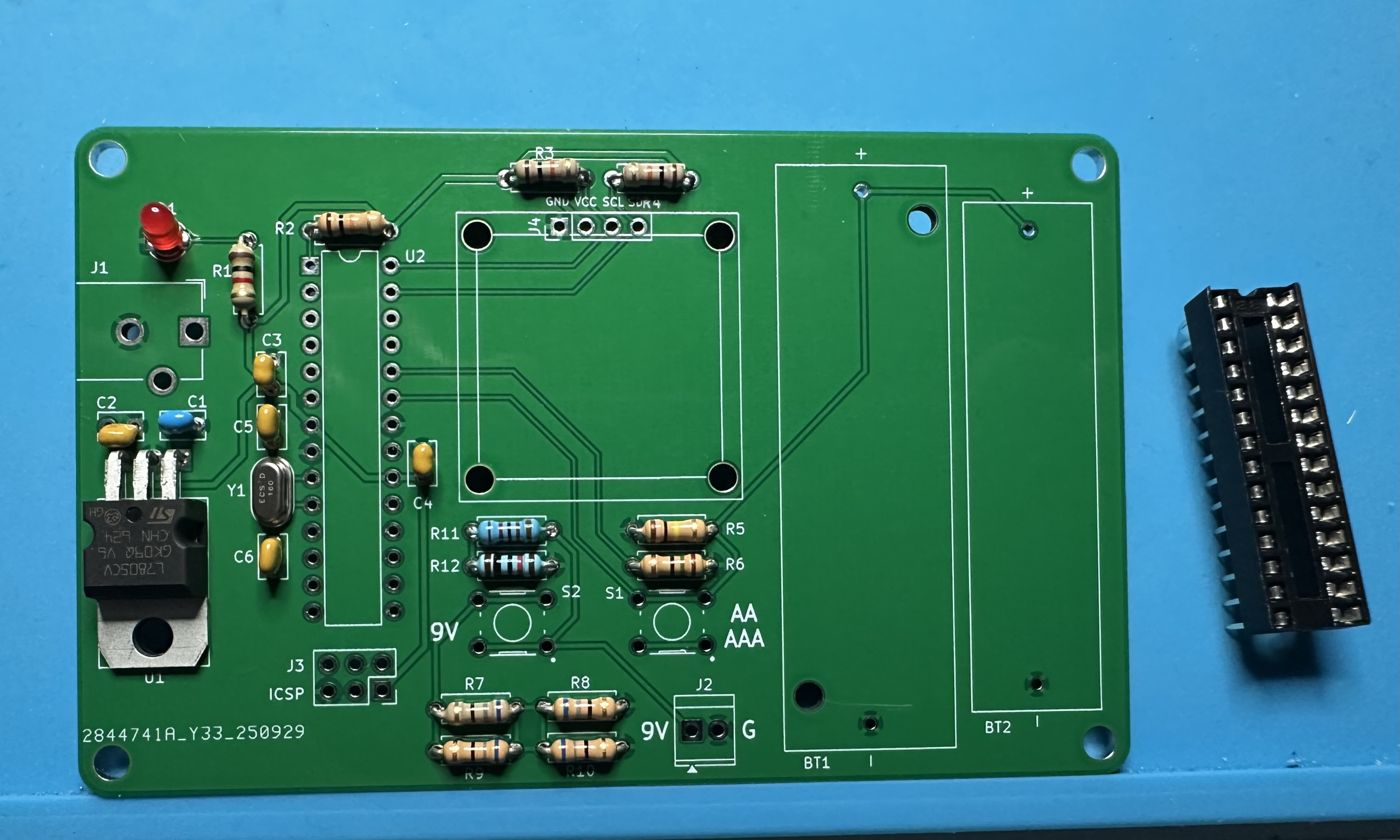
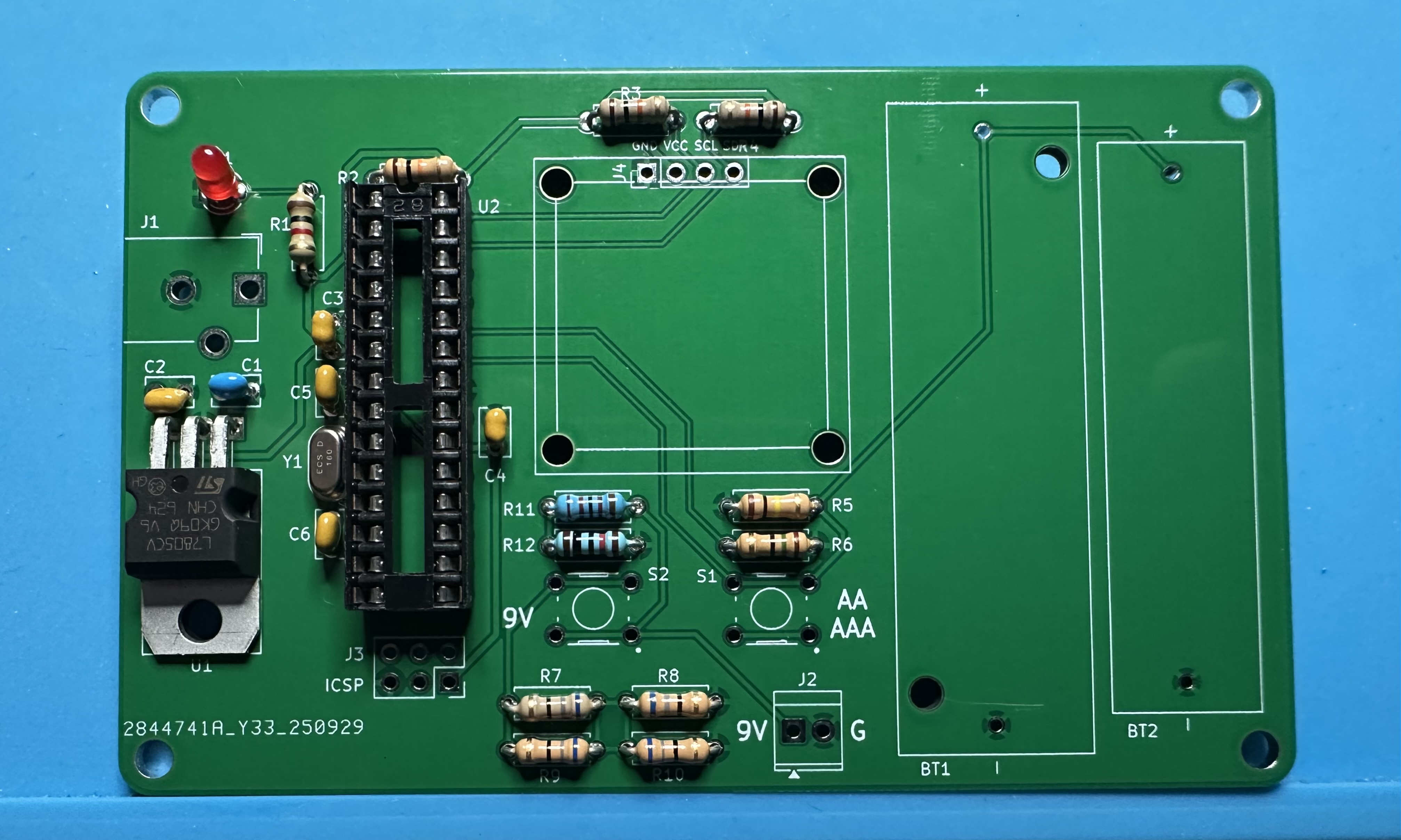
- Next up, add the chip socket — (U2) for the Atmega chip. This one is tedious — 28 pins. Solder one pin and check the alignment. Then take a deep breath and start soldering the other 27.
- Now try the two momentary switches that activate the current tests. Fitting the pins is a bit persnickety. If the pins are not fitting, rotate the switch by 90°. If needed, use pliers to straighten the pins a bit. The switches are symmetric so it doesn't matter if they are "up" or "down" — once you get them to fit in, they will work.
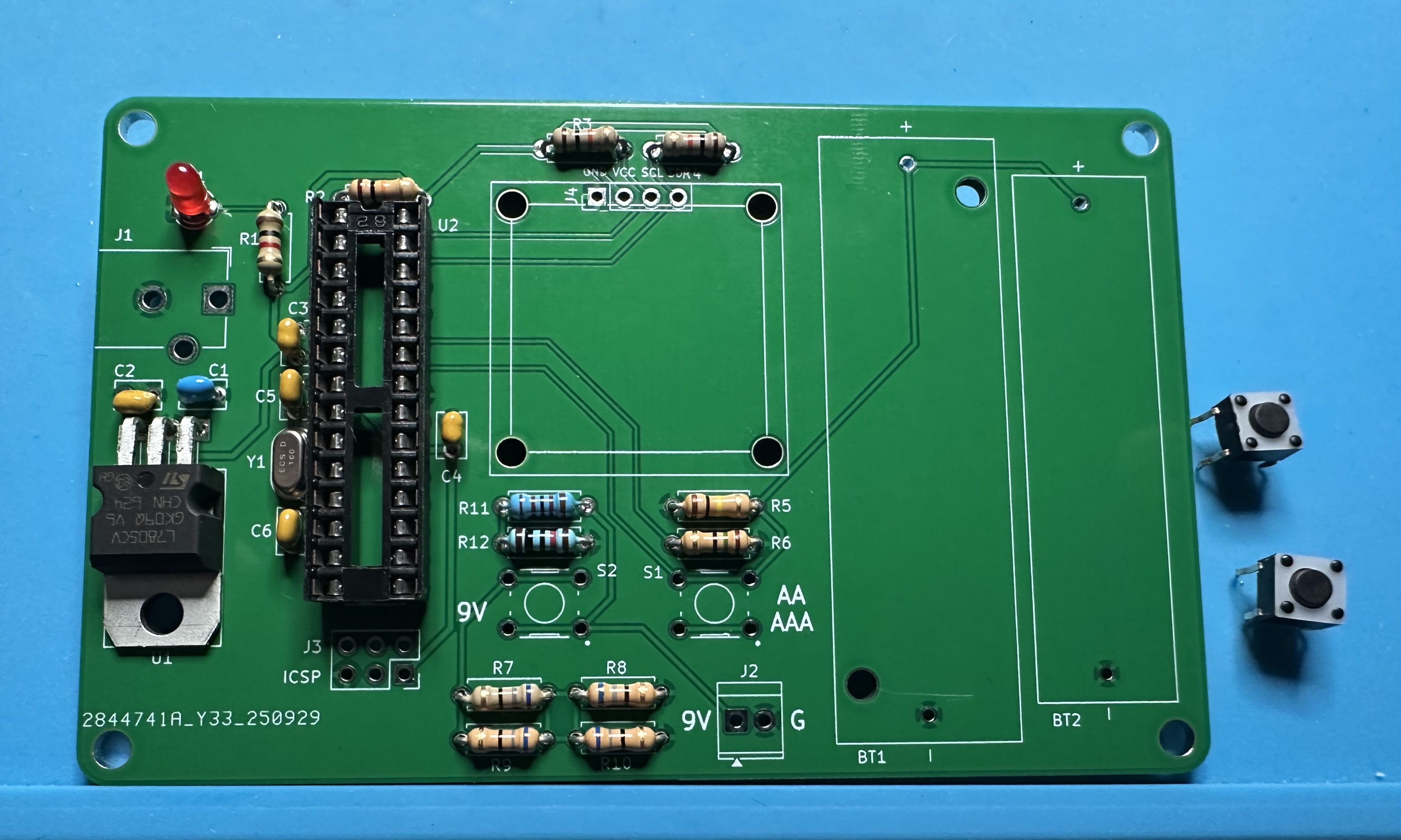
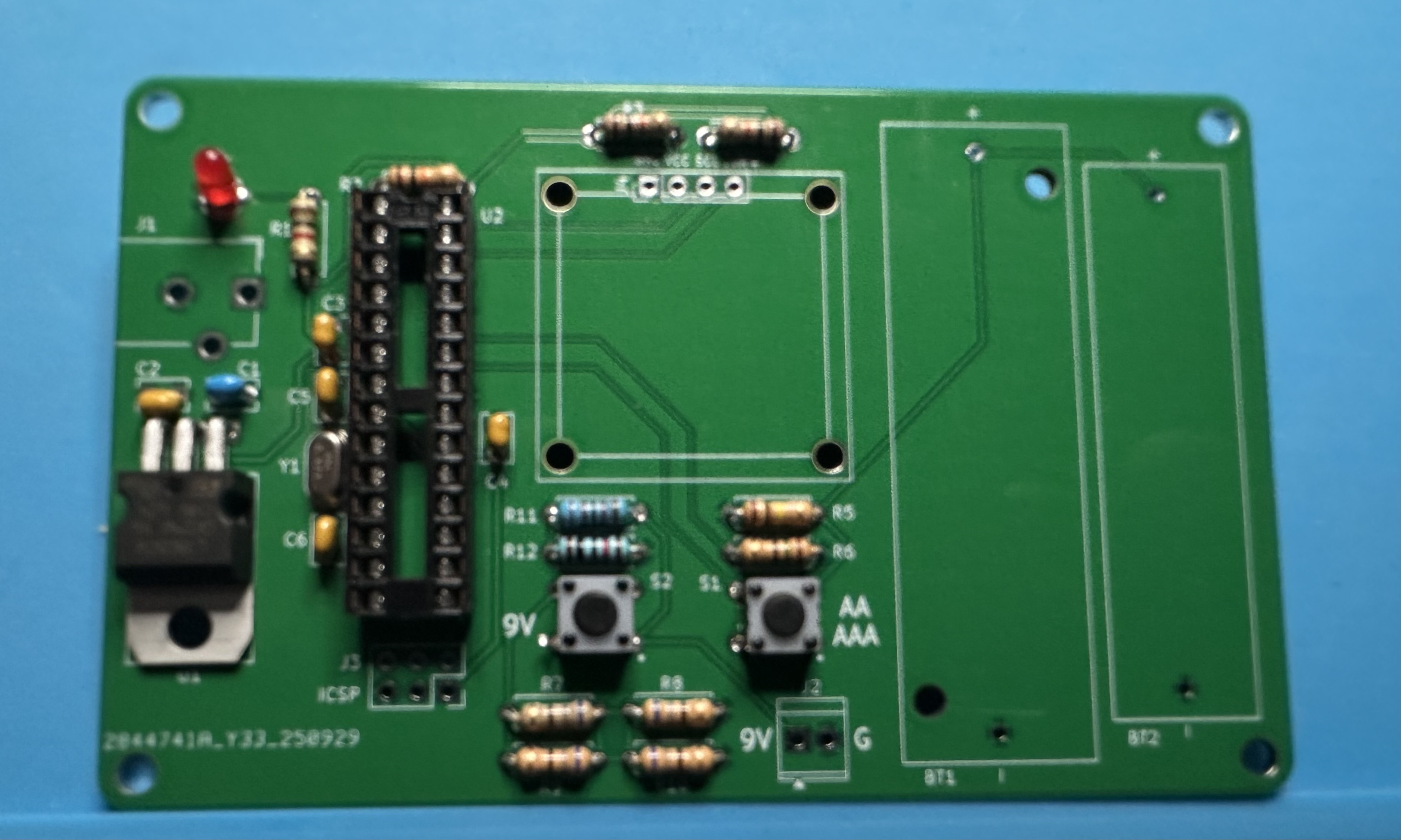
- Add the six-pin ICSP header, J3, for external programming.
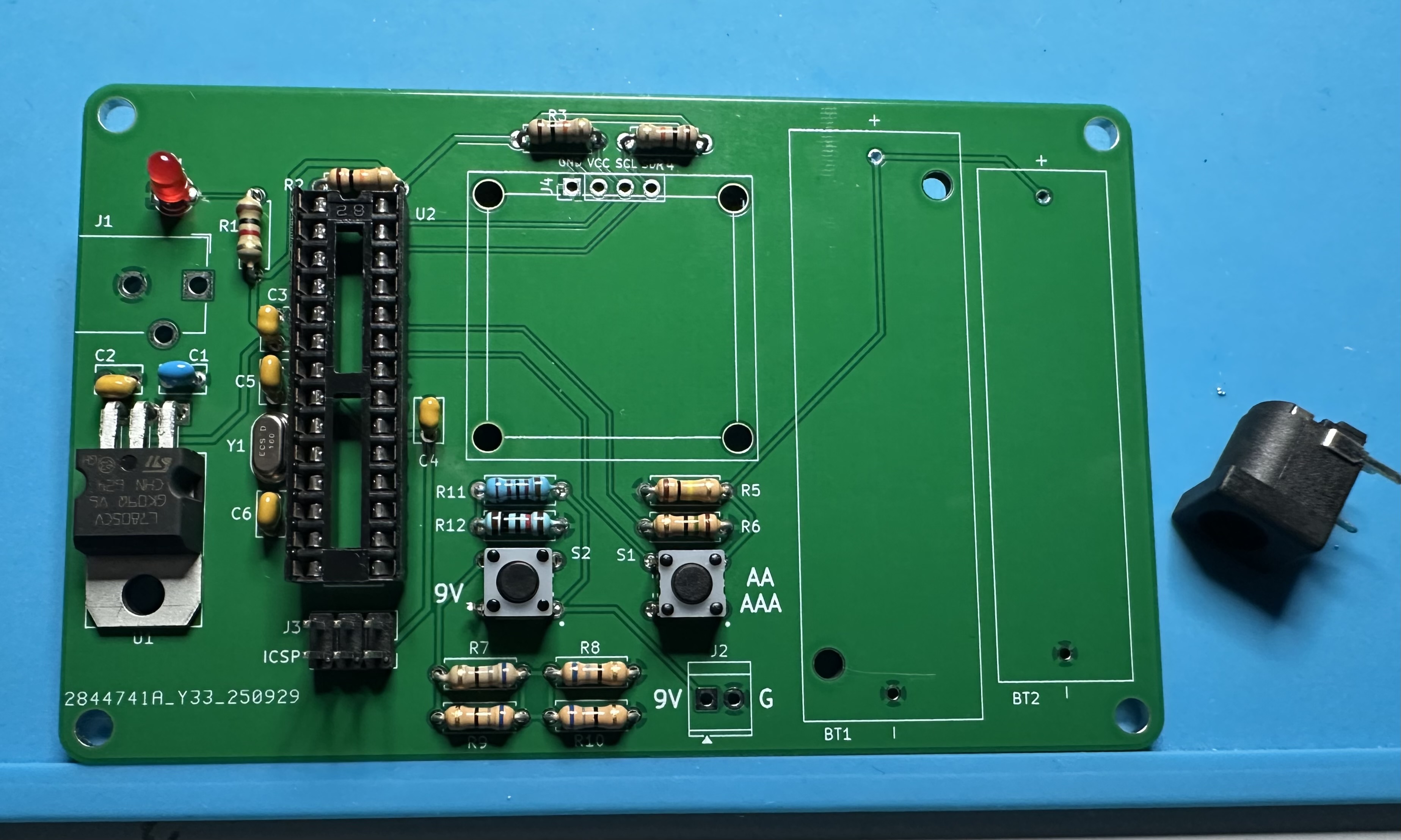
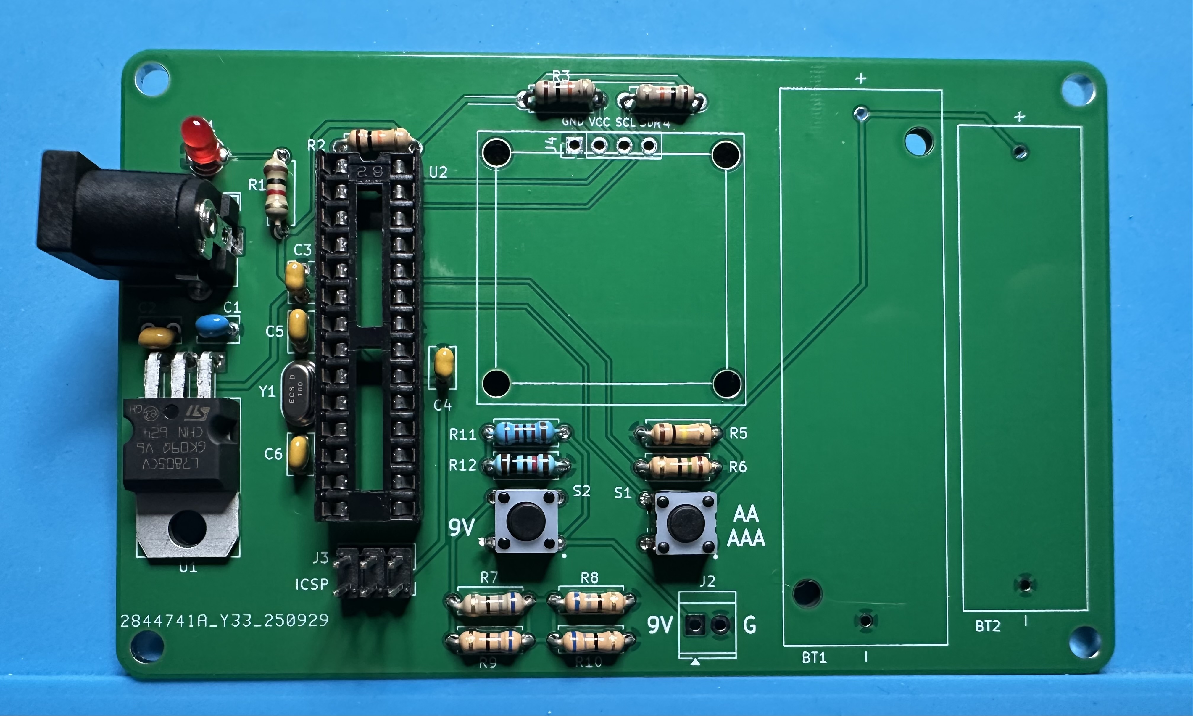
- Solder in the barrel-jack input.
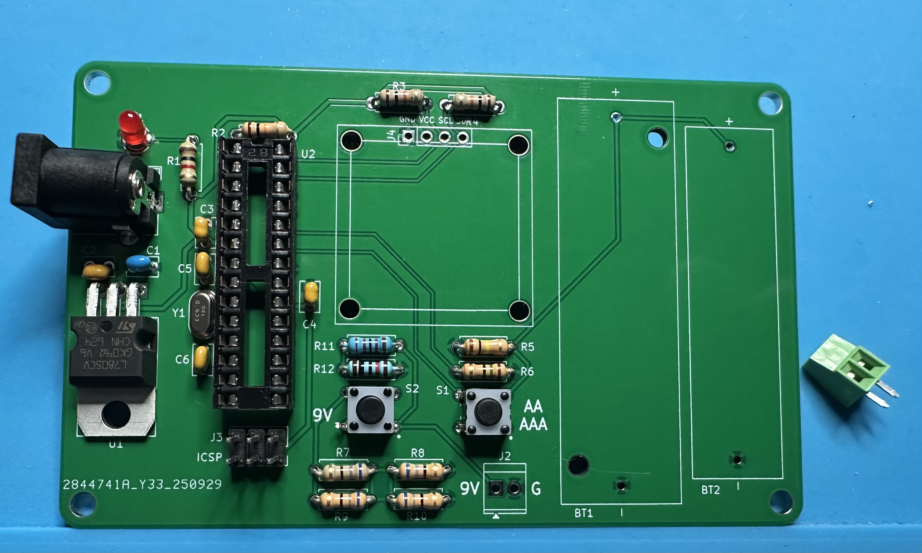
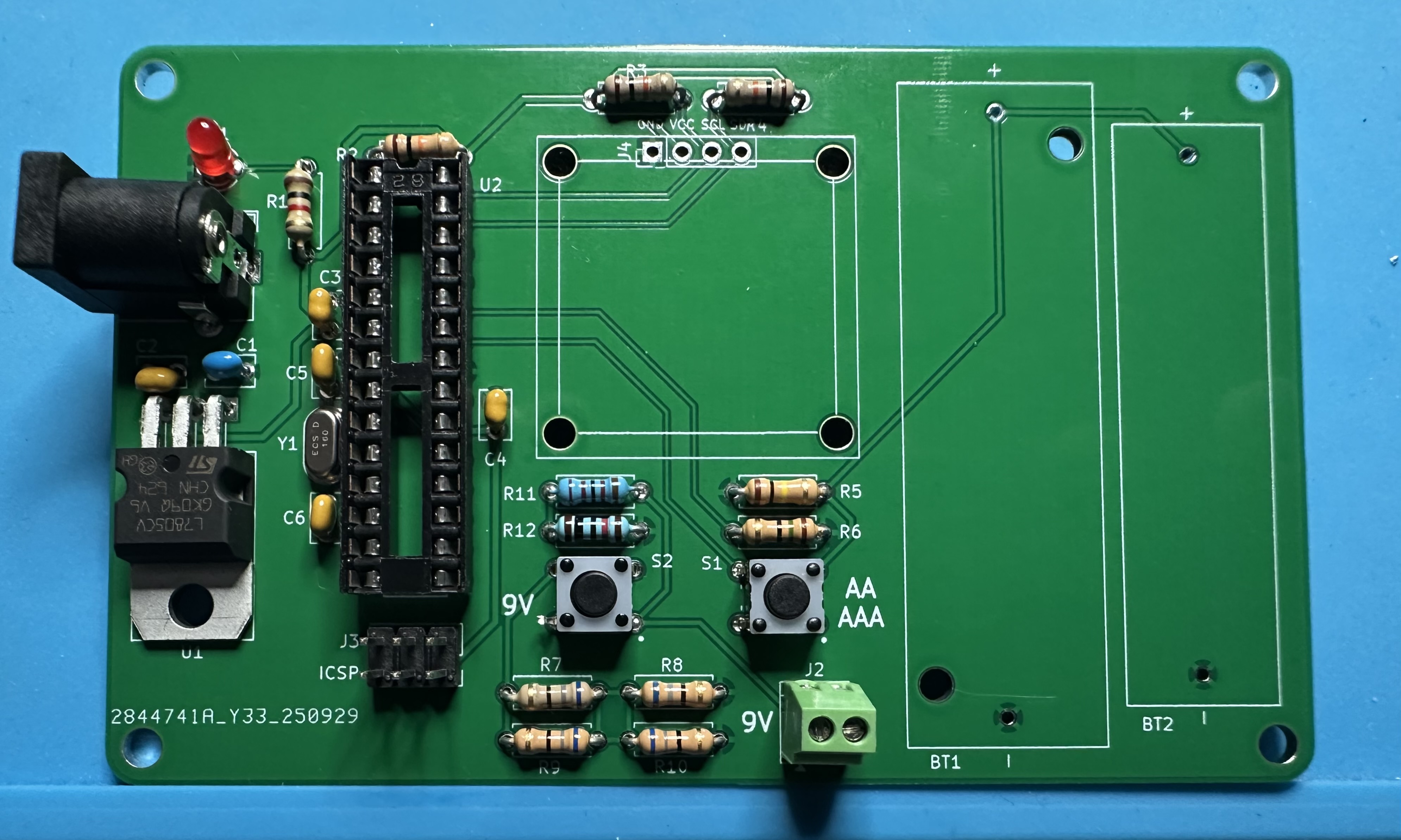
- Next, solder in the two-position terminal block used for connecting 9-V batteries.
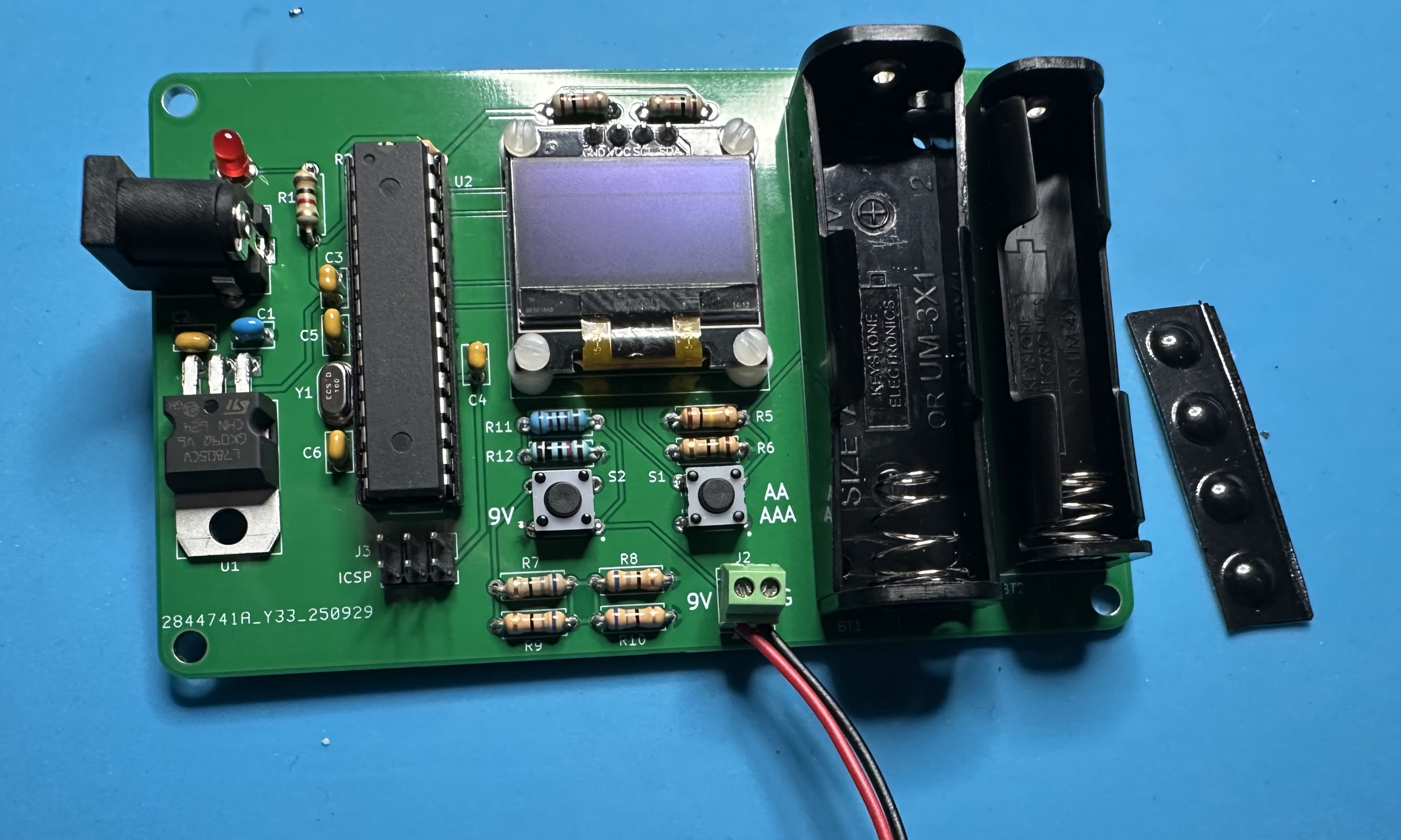
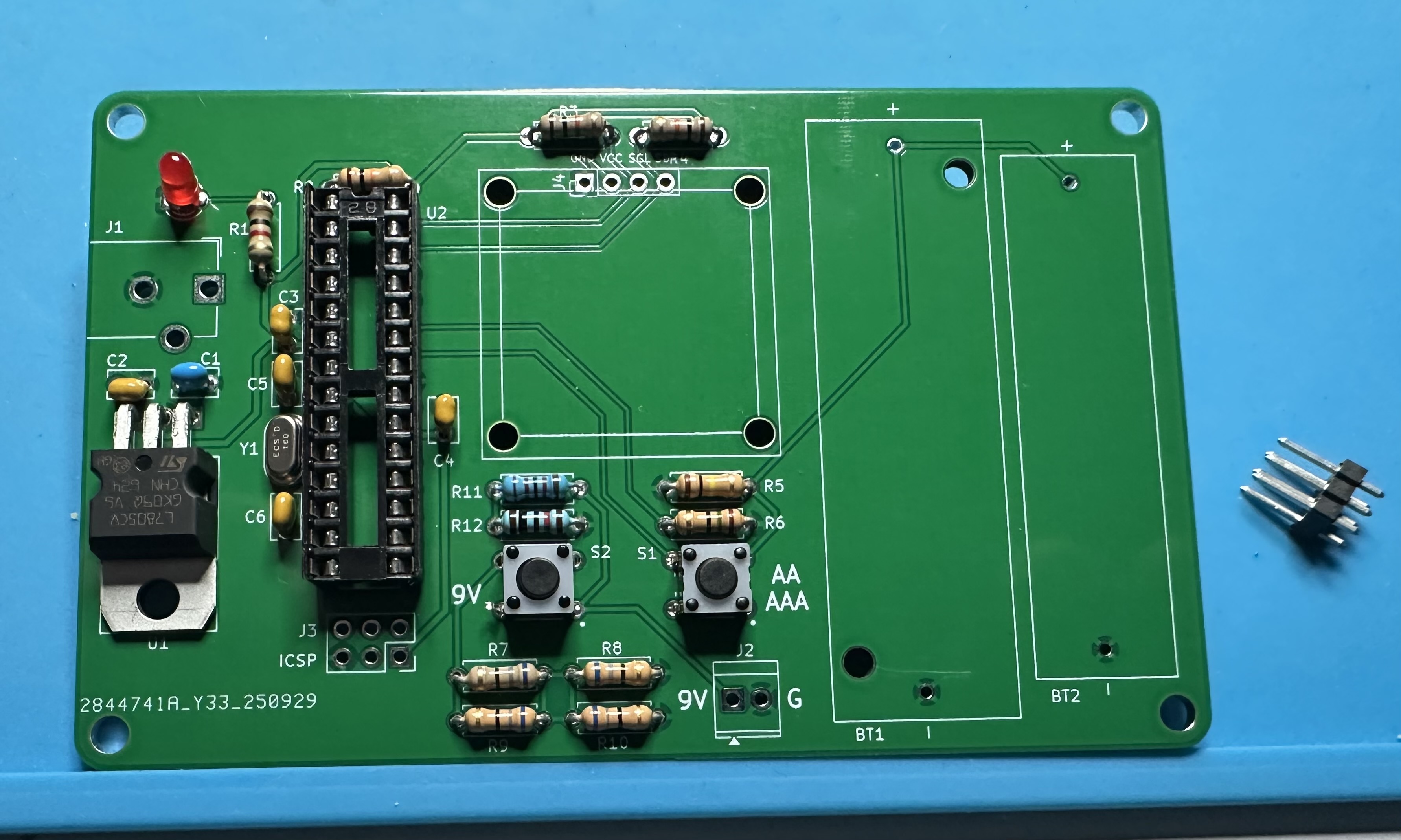
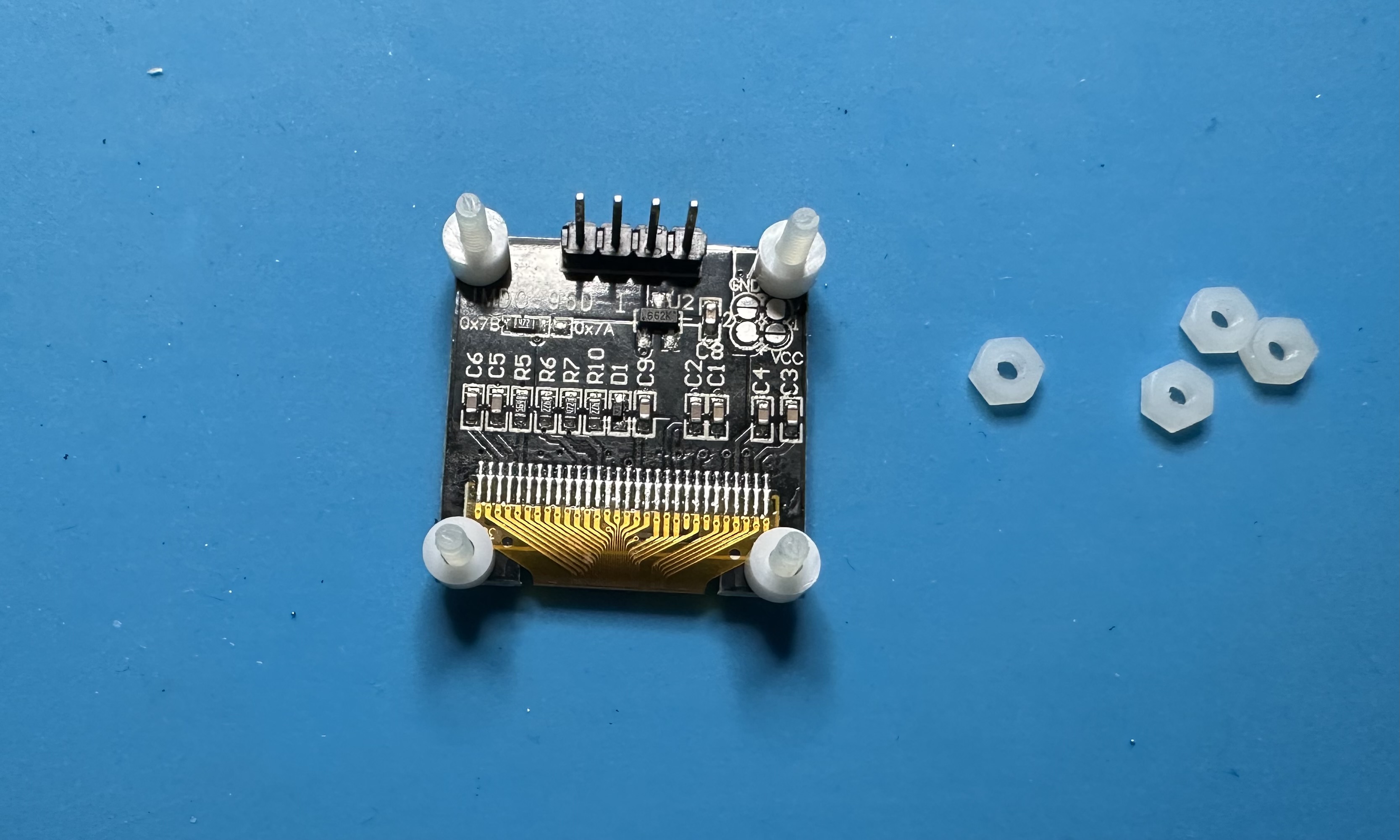
- We are redy to attach the OLED display and solder it in place. Suggested approach: Push all four of the nylon screws through the holes of the OLED board. It's a tight fit and you will need to apply a bit of force to get the screws through. (It will be OK!) Then turn the display over and put the four spacers on the screws. Next turn the PCB over and guide the four holes over the screws. Secure the OLED to the board by thread four nuts onto the screws — use a screw driver to tighten everything up. Finally, solder in the four pins for the display.
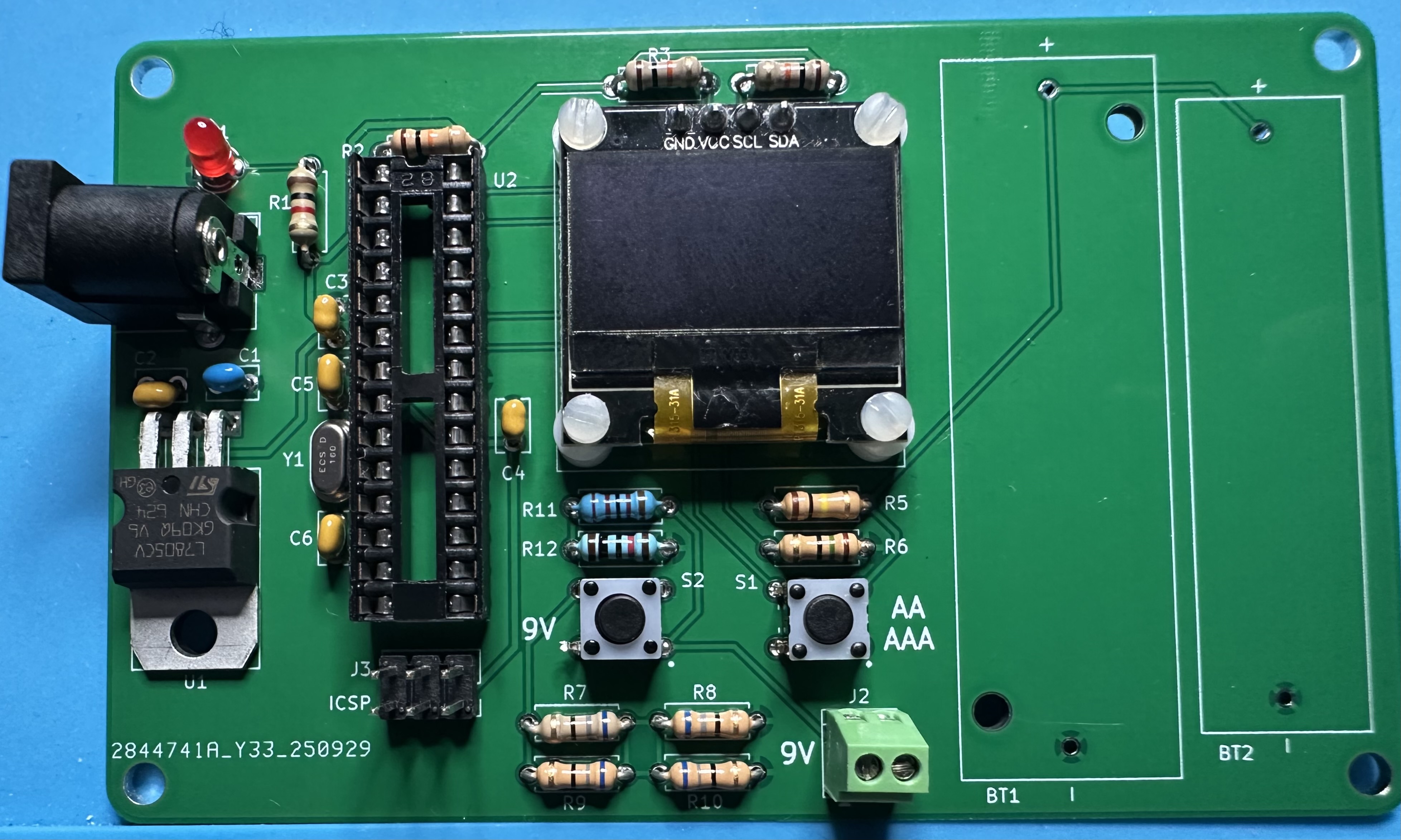
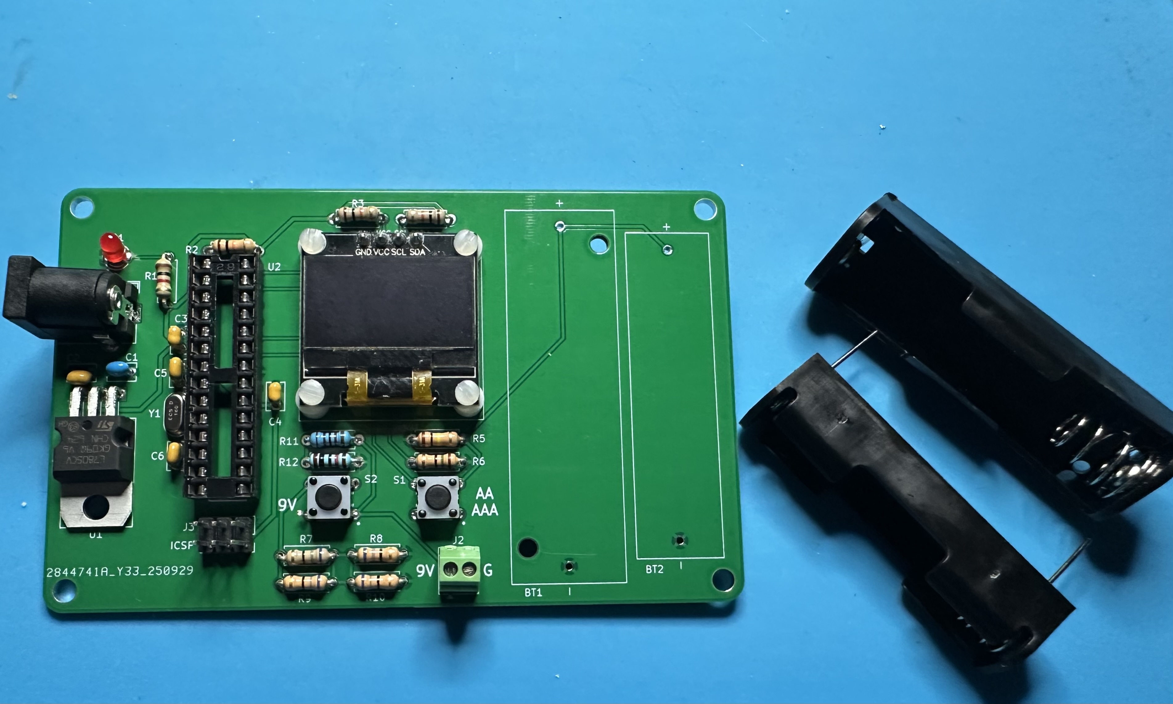
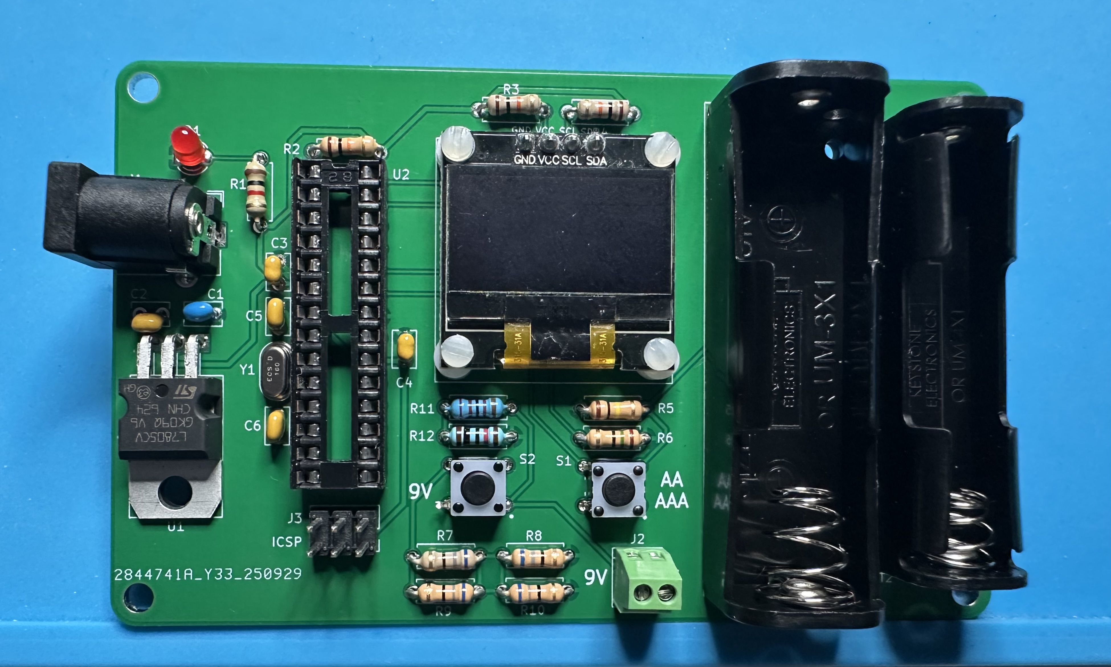
- For the final bit of soldering, attach the AA and AAA battery holders. It is pretty obvious where each goes. Be certain to keep positive and negative straight — both the board and the holders have positive and negative labels.
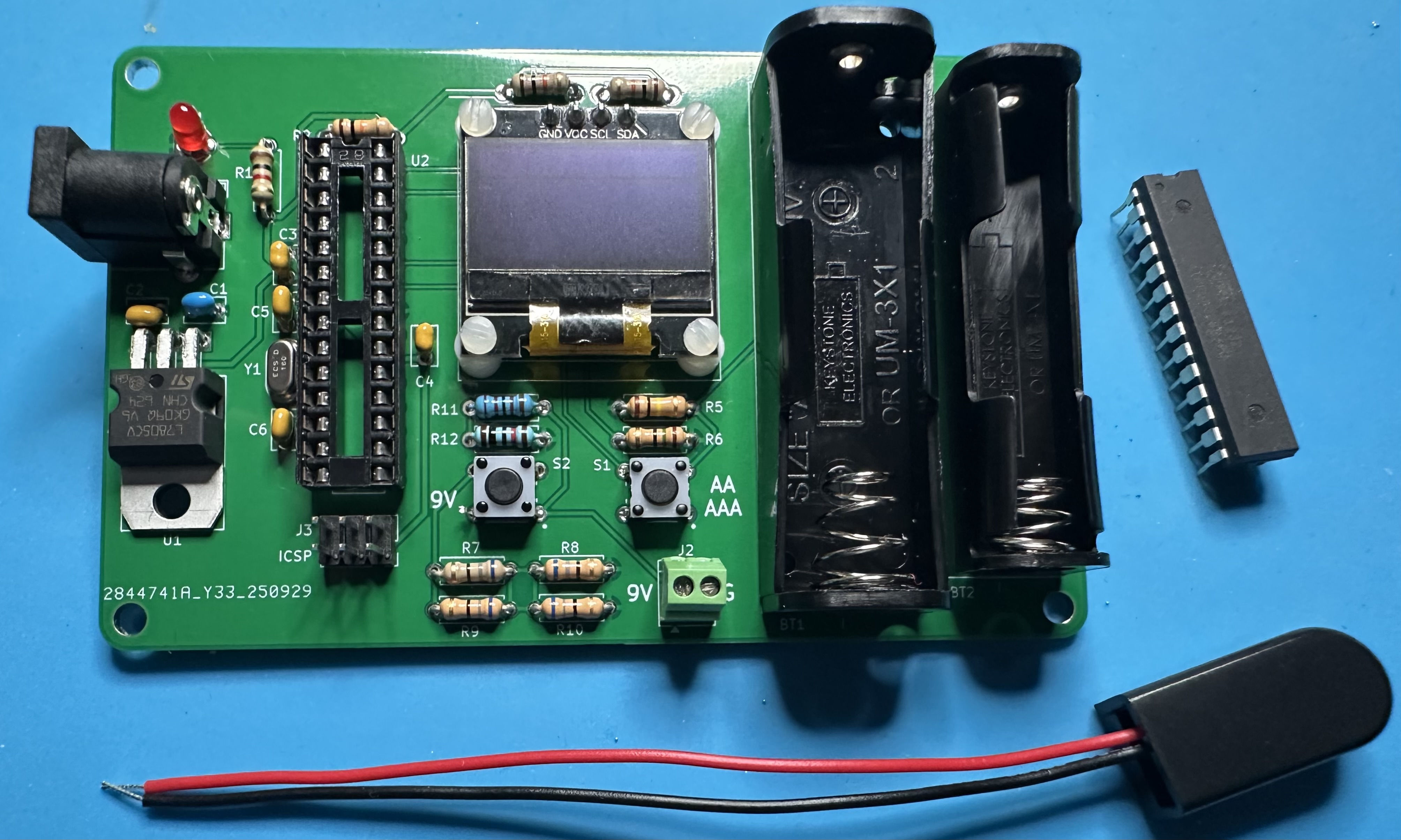
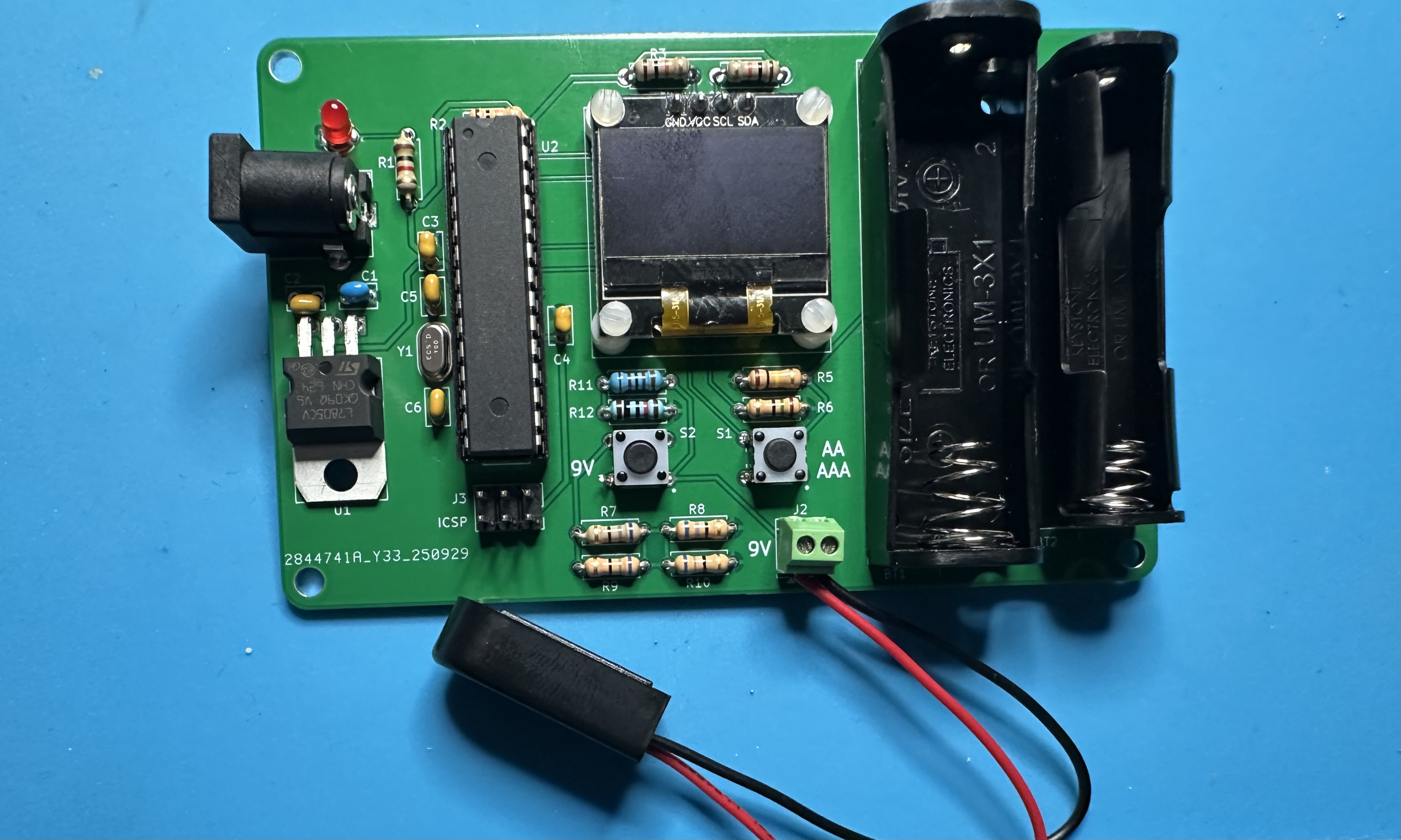
- To finish up, insert the Atmega328 chip into its socket. (Program it first, if you want.) As is typical, you may need to bend the pins inward a bit in order to get the chip to slide into the socket. The attach the leads for the 9-V battery strap to the terminal block — black wire to G (negative) and red wire to the "9 V" (positive) side.
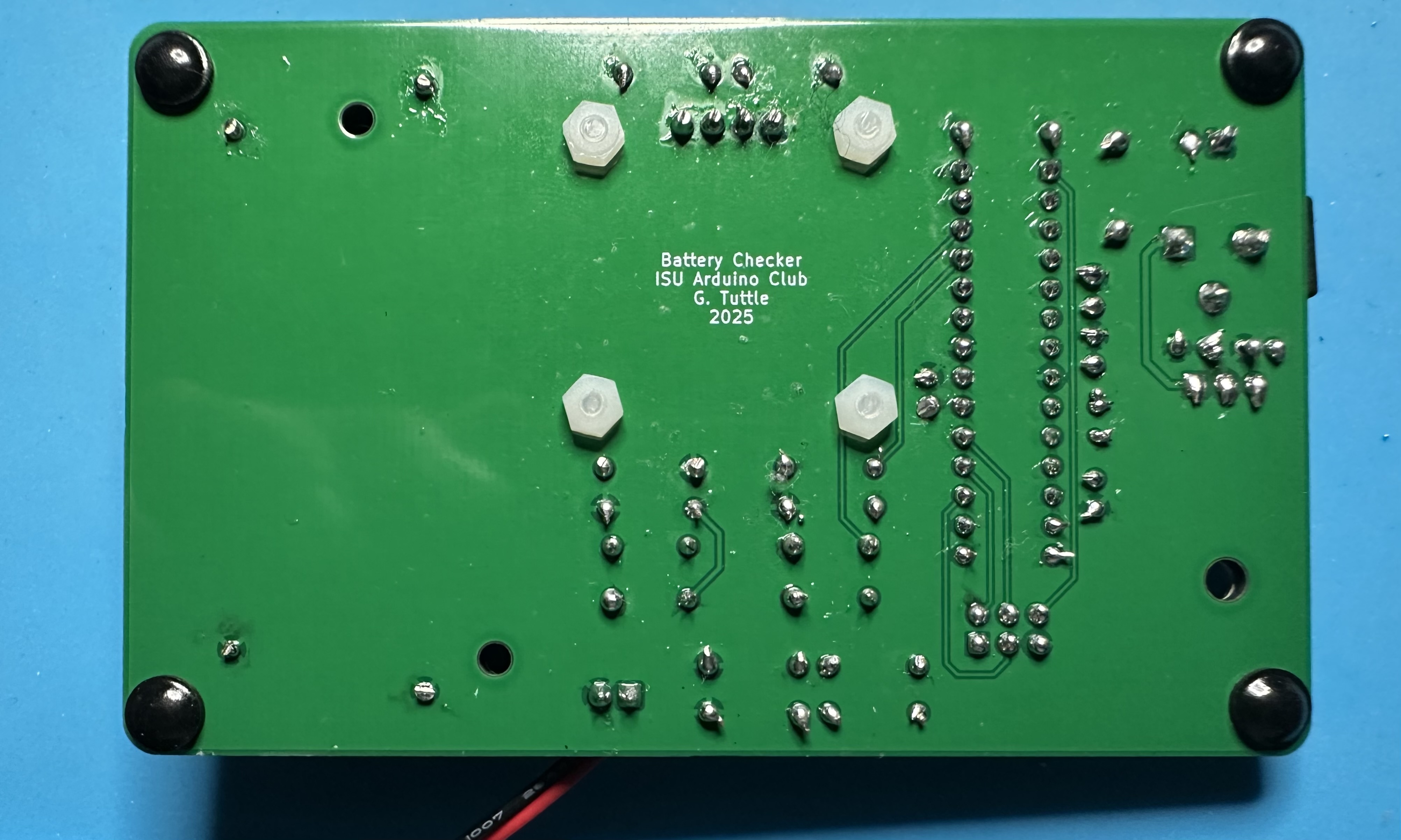
- If you'd like, attach 4 bumper feet to the bottom corners, so that the board sits level when you are using it. The bumpers won't be effective unless you trim off the excess length of the nylon screws and OLED leads, which extend out quite far. Wire cutters work fine for trimming the screws..